Answered step by step
Verified Expert Solution
Question
1 Approved Answer
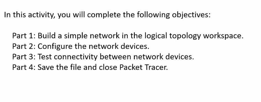
In this activity, you will complete the following objectives: Part 1: Build a simple network in the logical topology workspace. Part 2: Configure the network


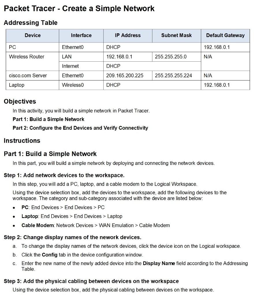
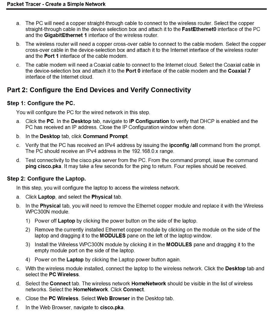
In this activity, you will complete the following objectives: Part 1: Build a simple network in the logical topology workspace. Part 2: Configure the network devices. Part 3: Test connectivity between network devices. Part 4: Save the file and close Packet Tracer. Packet Tracer - Create a Simple Network Addressing Table Device Interface IP Address Subnet Mask Default Gateway PC Etherneto DHCP 192.168.0.1 Wireless Router LAN 192.168.0.1 255.255.255.0 N/A Internet DHCP cisco.com Server Etherneto 209.165.200.225 255.255.255.224 N/A Laptop Wireless DHCP 192.168.0.1 Objectives In this activity, you will build a simple network in Packet Tracer. Part 1: Build a Simple Network Part 2: Configure the End Devices and Verify Connectivity Instructions Part 1: Build a Simple Network In this part, you will build a simple network by deploying and connecting the network devices. Step 1: Add network devices to the workspace. In this step, you will add a PC, laptop, and a cable modem to the Logical Workspace. Using the device selection box, add the devices to the workspace, add the following devices to the workspace. The category and sub-category associated with the device are listed below: PC: End Devices > End Devices > PC Laptop: End Devices > End Devices > Laptop Cable Modem: Network Devices > WAN Emulation > Cable Modem . a. Step 2: Change display names of the nework devices. To change the display names of the network devices, click the device icon on the Logical workspace. b. Click the Config tab in the device configuration window. C. Enter the new name of the newly added device into the Display Name field according to the Addressing Table. Step 3: Add the physical cabling between devices on the workspace Using the device selection box, add the physical cabling between devices on the workspace. Packet Tracer - Create a Simple Network a. The PC will need a copper straight-through cable to connect to the wireless router. Select the copper straight-through cable in the device selection box and attach it to the FastEtherneto interface of the PC and the GigabitEthernet 1 interface of the wireless router. b. The wireless router will need a copper cross-over cable to connect to the cable modem. Select the copper cross-over cable in the device-selection box and attach it to the Internet interface of the wireless router and the Port 1 interface of the cable modem. C. The cable modem will need a Coaxial cable to connect to the Internet cloud. Select the Coaxial cable in the device-selection box and attach it to the Port 0 interface of the cable modem and the Coaxial 7 interface of the Internet cloud. Part 2: Configure the End Devices and Verify Connectivity a. Step 1: Configure the PC. You will configure the PC for the wired network in this step. Click the PC. In the Desktop tab, navigate to IP Configuration to verify that DHCP is enabled and the PC has received an IP address. Close the IP Configuration window when done. b. In the Desktop tab, click Command Prompt. c. Verify that the PC has received an IPv4 address by issuing the ipconfig /all command from the prompt. The PC should receive an IPv4 address in the 192.168.0.x range. d. Test connectivity to the cisco.pka server from the PC. From the command prompt, issue the command ping cisco.pka. It may take a few seconds for the ping to return. Four replies should be received. Step 2: Configure the Laptop. In this step, you will configure the laptop to access the wireless network. a. Click Laptop, and select the Physical tab. b. In the Physical tab, you will need to remove the Ethernet copper module and replace it with the Wireless WPC300N module. 1) Power off Laptop by clicking the power button on the side of the laptop. 2) Remove the currently installed Ethernet copper module by clicking on the module on the side of the laptop and dragging it to the MODULES pane on the left of the laptop window. 3) Install the Wireless WPC300N module by clicking it in the MODULES pane and dragging it to the empty module port on the side of the laptop. 4) Power on the Laptop by clicking the Laptop power button again. c. With the wireless module installed, connect the laptop to the wireless network. Click the Desktop tab and select the PC Wireless. d. Select the connect tab. The wireless network HomeNetwork should be visible in the list of wireless networks. Select the HomeNetwork. Click Connect. Close the PC Wireless. Select Web Browser in the Desktop tab. f. In the Web Browser, navigate to cisco.pka. e
Step by Step Solution
There are 3 Steps involved in it
Step: 1

Get Instant Access to Expert-Tailored Solutions
See step-by-step solutions with expert insights and AI powered tools for academic success
Step: 2

Step: 3

Ace Your Homework with AI
Get the answers you need in no time with our AI-driven, step-by-step assistance
Get Started


