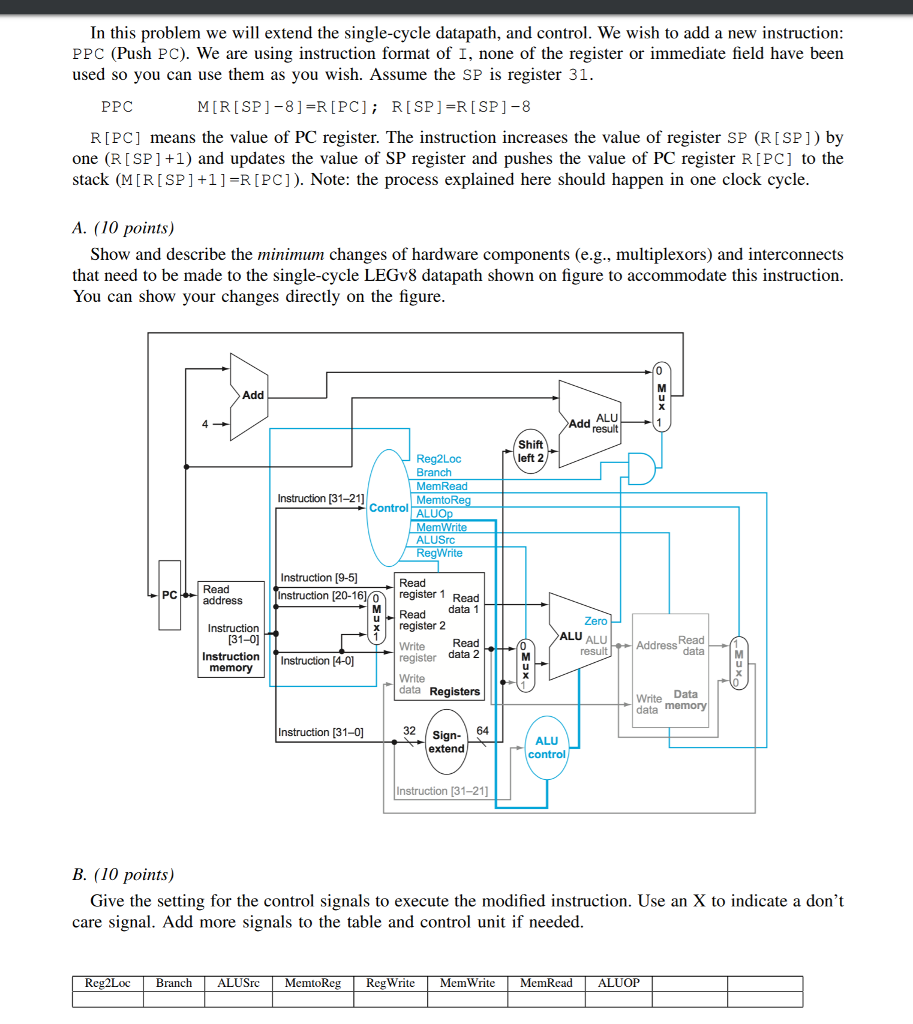
In this problem we will extend the single-cycle datapath, and control. We wish to add a new instruction: PPC (Push PC). We are using instruction format of I, none of the register or immediate field have been used so you can use them as you wish. Assume the SP is register 31. PPC M[R[SP]-8]=R[PC]; R[SP]=R[SP]-8 R[PC] means the value of PC register. The instruction increases the value of register SP (R[SP]) by one (R[SP]+1) and updates the value of SP register and pushes the value of PC register R[PC] to the stack (M[R[SP]+1]=R[PC]). Note: the process explained here should happen in one clock cycle.
A. (10 points) Show and describe the minimum changes of hardware components (e.g., multiplexors) and interconnects that need to be made to the single-cycle LEGv8 datapath shown on figure to accommodate this instruction. You can show your changes directly on the figure.
B. (10 points) Give the setting for the control signals to execute the modified instruction. Use an X to indicate a dont care signal. Add more signals to the table and control unit if needed. 
In this problem we will extend the single-cycle datapath, and control. We wish to add a new instruction PPC (Push PC). We are using instruction format of I, none of the register or immediate field have been used so you can use them as you wish. Assume the SP is register 31. PPC MIR[SPJ-81-R [PC ] ; R[SP]=R [ SP ]-8 RIPC] means the value of PC register. The instruction increases the value of register SP (RISP]) by one (RISP] +1) and updates the value of SP register and pushes the value of PC register RIPC] to the stack (M[RISP] +1]-R[PC]). Note: the process explained here should happen in one clock cycle A. (10 points) Show and describe the minimum changes of hardware components (e.g., multiplexors) and interconnects that need to be made to the single-cycle LEGv8 datapath shown on figure to accommodate this instruction. You can show your changes directly on the figure Add Add ALU Shift left 2 MemRead MemtoRe Instruction [31-21] Control AL ALUSrc egWrite Instruction [9-5] Read PCRead Instruction [20-16 register 1 Read uRead data1 Write Read address MI xregister 2 31-0 Instruction Instruction [4-0] resultAddress Read register data 2 data Registers Write Data data memory Instruction [31-0] 32 Sign- 64 ALU Instruction [31-21] B. (10 points) Give the setting for the control signals to execute the modified instruction. Use an X to indicate a don't care signal. Add more signals to the table and control unit if needed. Reg2LocBranch LUSrcMemtoReg RegWriteMemWrite Mem In this problem we will extend the single-cycle datapath, and control. We wish to add a new instruction PPC (Push PC). We are using instruction format of I, none of the register or immediate field have been used so you can use them as you wish. Assume the SP is register 31. PPC MIR[SPJ-81-R [PC ] ; R[SP]=R [ SP ]-8 RIPC] means the value of PC register. The instruction increases the value of register SP (RISP]) by one (RISP] +1) and updates the value of SP register and pushes the value of PC register RIPC] to the stack (M[RISP] +1]-R[PC]). Note: the process explained here should happen in one clock cycle A. (10 points) Show and describe the minimum changes of hardware components (e.g., multiplexors) and interconnects that need to be made to the single-cycle LEGv8 datapath shown on figure to accommodate this instruction. You can show your changes directly on the figure Add Add ALU Shift left 2 MemRead MemtoRe Instruction [31-21] Control AL ALUSrc egWrite Instruction [9-5] Read PCRead Instruction [20-16 register 1 Read uRead data1 Write Read address MI xregister 2 31-0 Instruction Instruction [4-0] resultAddress Read register data 2 data Registers Write Data data memory Instruction [31-0] 32 Sign- 64 ALU Instruction [31-21] B. (10 points) Give the setting for the control signals to execute the modified instruction. Use an X to indicate a don't care signal. Add more signals to the table and control unit if needed. Reg2LocBranch LUSrcMemtoReg RegWriteMemWrite Mem


