Question
#include msp.h #include CortexM.c void main() { Clock_Init48MHz(); //P1.1 set tp GPIO input P1->SEL0 &= ~0X02; P1->SEL1 &= ~0X02; P1->DIR &= ~0X02; P1->REN |= 0X02;


#include "msp.h" #include "CortexM.c"
void main() { Clock_Init48MHz(); //P1.1 set tp GPIO input P1->SEL0 &= ~0X02; P1->SEL1 &= ~0X02; P1->DIR &= ~0X02; P1->REN |= 0X02; P1->DS |= 0X02; P1->OUT |= 0X02;
// P1.4 set to GPIO input P1->SEL0 &= ~0X01; P1->SEL1 &= ~0X01; P1->DIR &= ~0X01; P1->REN |= 0X01; P1->OUT |= 0X01; // P2.0 set to GPIO input P2->SEL0 &= ~0X01; P2->SEL1 &= ~0X01; P2->DIR &= ~0X01; P2->REN |= 0X01; P2->DS |= 0X01; P2->OUT |= 0X01;
delay (100); int activate =0; while(1) { if(!(P1-> IN & 0X02)) { P2->OUT |= 0X01; } if (P1-> IN & 0X02){ P2->OUT = 0X02; } }
} This is my code but it keeps giving me an error. and it is not working. I need help to write the correct code for this. I used msp432 and code composer studio.
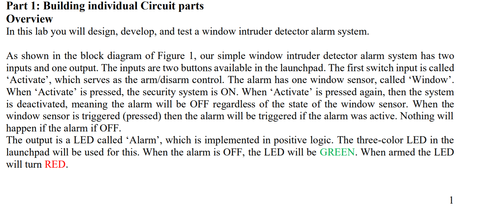
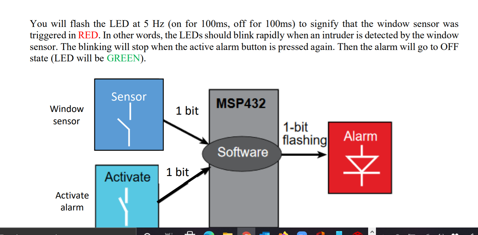
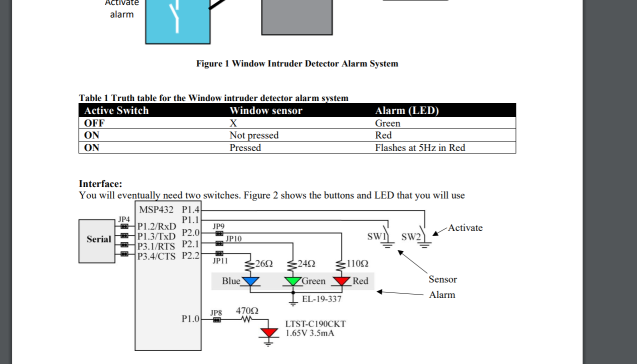
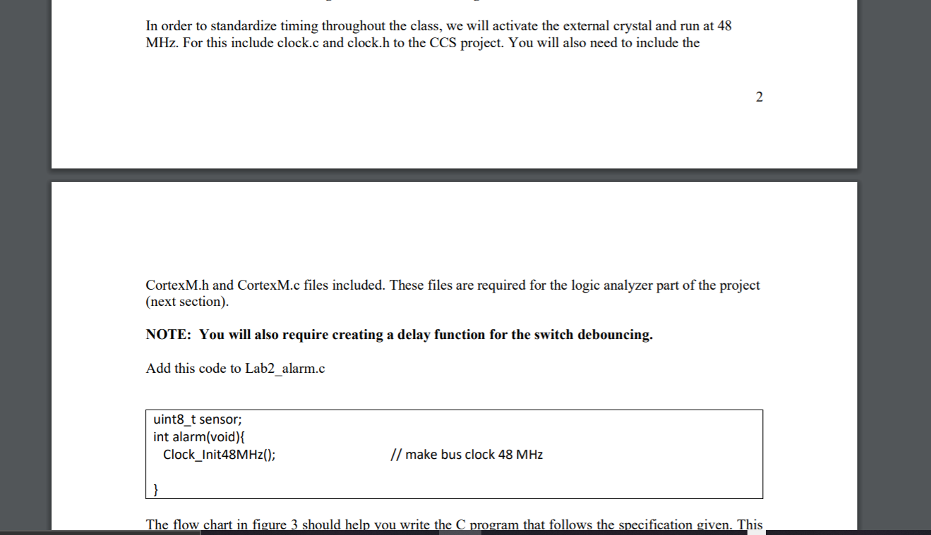
Part 1: Building individual Circuit parts Overview In this lab you will design, develop, and test a window intruder detector alarm system. As shown in the block diagram of Figure 1, our simple window intruder detector alarm system has two inputs and one output. The inputs are two buttons available in the launchpad. The first switch input is called Activate', which serves as the arm/disarm control. The alarm has one window sensor, called Window'. When Activate is pressed, the security system is ON. When Activate is pressed again, then the system is deactivated, meaning the alarm will be OFF regardless of the state of the window sensor. When the window sensor is triggered (pressed) then the alarm will be triggered if the alarm was active. Nothing will happen if the alarm if OFF. The output is a LED called Alarm', which is implemented in positive logic. The three-color LED in the launchpad will be used for this. When the alarm is OFF, the LED will be GREEN. When armed the LED will turn RED. 1 You will flash the LED at 5 Hz (on for 100ms, off for 100ms) to signify that the window sensor was triggered in RED. In other words, the LEDs should blink rapidly when an intruder is detected by the window sensor. The blinking will stop when the active alarm button is pressed again. Then the alarm will go to OFF state (LED will be GREEN). Sensor MSP432 Window 1 bit sensor 1-bit flashing Alarm Software Activate 1 bit Activate alarm Activate alarm Figure 1 Window Intruder Detector Alarm System Table 1 Truth table for the Window intruder detector alarm system Active Switch Window sensor OFF X ON Not pressed ON Pressed Alarm (LED) Green Red Flashes at 5Hz in Red Interface: You will eventually need two switches. Figure 2 shows the buttons and LED that you will use MSP432 P1.4 JP4 P1.1 P1.2/RxD JP9 Activate P2.0 Serial P1.3/TxD JP10 SW1 SW2 P3.1/RTS P2.1 * P3.4/CTS P2.2 JPII 2692 32402 -110 Blue V Green Red Sensor EL-19-337 Alarm JP8 47092 P1.00 LTST-C190CKT 1.65V 3.5mA In order to standardize timing throughout the class, we will activate the external crystal and run at 48 MHz. For this include clock.c and clock.h to the CCS project. You will also need to include the 2. CortexM.h and CortexM.c files included. These files are required for the logic analyzer part of the project (next section). NOTE: You will also require creating a delay function for the switch debouncing. Add this code to Lab2 alarm.c uint8_t sensor; int alarm(void) { Clock_Init48MHz(); // make bus clock 48 MHz The flow chart in figure 3 should help you write the C program that follows the specification given. This Part 1: Building individual Circuit parts Overview In this lab you will design, develop, and test a window intruder detector alarm system. As shown in the block diagram of Figure 1, our simple window intruder detector alarm system has two inputs and one output. The inputs are two buttons available in the launchpad. The first switch input is called Activate', which serves as the arm/disarm control. The alarm has one window sensor, called Window'. When Activate is pressed, the security system is ON. When Activate is pressed again, then the system is deactivated, meaning the alarm will be OFF regardless of the state of the window sensor. When the window sensor is triggered (pressed) then the alarm will be triggered if the alarm was active. Nothing will happen if the alarm if OFF. The output is a LED called Alarm', which is implemented in positive logic. The three-color LED in the launchpad will be used for this. When the alarm is OFF, the LED will be GREEN. When armed the LED will turn RED. 1 You will flash the LED at 5 Hz (on for 100ms, off for 100ms) to signify that the window sensor was triggered in RED. In other words, the LEDs should blink rapidly when an intruder is detected by the window sensor. The blinking will stop when the active alarm button is pressed again. Then the alarm will go to OFF state (LED will be GREEN). Sensor MSP432 Window 1 bit sensor 1-bit flashing Alarm Software Activate 1 bit Activate alarm Activate alarm Figure 1 Window Intruder Detector Alarm System Table 1 Truth table for the Window intruder detector alarm system Active Switch Window sensor OFF X ON Not pressed ON Pressed Alarm (LED) Green Red Flashes at 5Hz in Red Interface: You will eventually need two switches. Figure 2 shows the buttons and LED that you will use MSP432 P1.4 JP4 P1.1 P1.2/RxD JP9 Activate P2.0 Serial P1.3/TxD JP10 SW1 SW2 P3.1/RTS P2.1 * P3.4/CTS P2.2 JPII 2692 32402 -110 Blue V Green Red Sensor EL-19-337 Alarm JP8 47092 P1.00 LTST-C190CKT 1.65V 3.5mA In order to standardize timing throughout the class, we will activate the external crystal and run at 48 MHz. For this include clock.c and clock.h to the CCS project. You will also need to include the 2. CortexM.h and CortexM.c files included. These files are required for the logic analyzer part of the project (next section). NOTE: You will also require creating a delay function for the switch debouncing. Add this code to Lab2 alarm.c uint8_t sensor; int alarm(void) { Clock_Init48MHz(); // make bus clock 48 MHz The flow chart in figure 3 should help you write the C program that follows the specification given. ThisStep by Step Solution
There are 3 Steps involved in it
Step: 1

Get Instant Access to Expert-Tailored Solutions
See step-by-step solutions with expert insights and AI powered tools for academic success
Step: 2

Step: 3

Ace Your Homework with AI
Get the answers you need in no time with our AI-driven, step-by-step assistance
Get Started


