Answered step by step
Verified Expert Solution
Question
1 Approved Answer
Introduction to the Experiment Evaporation of moisture into air, which is driven by differences in moisture content levels, requires large amount of heat to


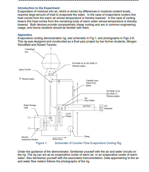
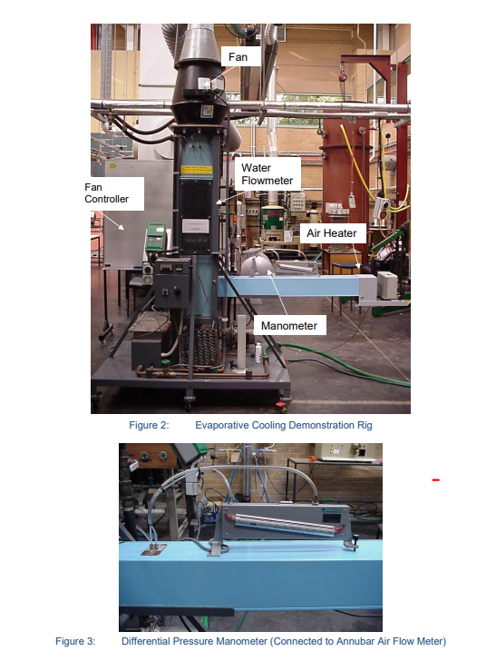
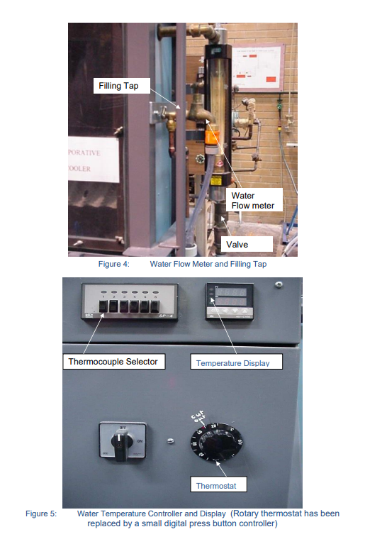
Introduction to the Experiment Evaporation of moisture into air, which is driven by differences in moisture content levels, requires large amount of heat to evaporate the water. In the case of evaporative coolers this heat comes from the warm air whose temperature is thereby lowered. In the case of cooling towers this heat comes from the remaining body of warm water whose temperature is thereby lowered. Both devices provide comparatively cheap cooling and are in common engineering usage, and hence students should be familiar with them. Apparatus Evaporative cooling demonstration rig, see schematic in Fig 1, and photographs in Figs 2-6. This rig was designed and constructed as a final year project by two former students, Morgan Woodfield and Robert Tarento. Centrifugal Fan Spray Nozzle Thermocouple Water Storage Tank Level Gauge Wet Bulb (6) & Dry Bulb (3) Thermocouples Variable Area Water Flow Meter Air Flow Meter Air Flow Wet Bulb (4) & Dry Bulb (5) Thermocouples Air Preheater Electric Immersion Heaters Figure 1: Water Flow Pump Schematic of Counter Flow Evaporative Cooling Rig Under the guidance of the demonstrator, familiarise yourself with the air and water circuits on the rig. The rig can act as an evaporative cooler of warm air, or an evaporative cooler of warm water. Also familiarise yourself with the associated instrumentation. Data appertaining to the air and water flow meters follows the photographs of the rig. Fan Fan Controller Water Flowmeter Air Heater Manometer Figure 2: Evaporative Cooling Demonstration Rig Figure 3: Differential Pressure Manometer (Connected to Annubar Air Flow Meter) Figure 5: PORATIVE OOLER Filling Tap Water Flow meter Valve Figure 4: Water Flow Meter and Filling Tap Thermocouple Selector Temperature Display but Thermostat Water Temperature Controller and Display (Rotary thermostat has been replaced by a small digital press button controller) Figure 6: Variable Frequency Fan Controller (this has now been replaced with a Hitachi unit that is integral with the rig) Water Flow meter The water flow meter is a Fischer & Porter variable area flow meter, Tube No. FP-1-35-G10/83, Float No. 1-GSVGT-69. 100% Flow = 0.599 kg/sec if the water has a density of 1000 kg/m. To correct for other densities of water: . mata mead as if is 1000 kg/ (Po - Pac)P (P-1000 )1000 where p = actual density of water in your experiments, in kg/m. Pstainless steel float density 8020 kg/m. Air Flow meter The air flow meter is an "Annubar Airbar" Model Air 26, fitted in a duct whose internal dimensions are approximately 0.148 x 0.148 m. The "Airbar" is a "self-averaging pitot tube" that has ports that sense upstream total pressure and down stream pressure. In a normal pitot- static tube upstream total pressure and the static pressure are sensed and, for incompressible flow, their difference App. In the "Airbar" the Ap is greater due to the low pressure on the downstream side. Ap = 1 2 * where K = 0.65 for the Airbar in use here Thus Ap = 2.37 xp i.e. an amplification of 2.37 compared to a pitot-static Ap. This Ap is measured using a manometer indicating mm of water height, hw. h Therefore, Ap = P.8 2.37 1000 Taking p, as 1000 kg/m and g as 9.81 m/sec 2 x 9.81 x h, V = And mair =P VA 2.37 Pa 2x9.81h P Therefore, A & A=0.0219m [= 0.1487] 2.37 mar=0.0630 Par To find look up v = air on the psychrometric chart. Experimental Procedure 1st experiment - Evaporative Cooling of Warm Air. The demonstrator will have set the rig up (following the instructions in part A of this appendix) with warm air entering it so that the rig may be demonstrated as an evaporative cooler. The pump and fan will have been started before your arrival in order that the water tank temperature may come to equilibrium. The water flow rate, which is regulated by the ball valve before the flow meter, should be about 57% on the flowmeter scale. The air flow meter should give about 24 mm water gauge on the inclined manometer; air flow is regulated with the fan speed control for which a setting of about 38 Hz should give the desired flow. Do not exceed 50 Hz on the fan speed control or 25 mm water gauge on the manometer. The suggested settings should result in approximately equal air and water mass flow rates, (ie "LG" = 1). Students are to take two sets of readings of temperatures and flows over a 5 minute interval, and record them in the table provided. Students are to stop the fan, then stop the pump and quickly shut the ball valve in the pump's suction line. Using a measuring flask carefully refill the sump via the perspex level gauge to the 125mm mark. Before proceeding to the next experiment, students are to sketch a temperature versus distance distribution for the evaporative cooler, showing water and wet and dry bulb air temperature readings. Table of Measurements Summarise your results with the following table: Air Wet Bulb Air Dry Bulb Exp't Water No. Inlet T2 Water Outlet T1 Inlet T4 Outlet T6 Inlet T5 Water Outlet T3 Flow% Air Flow mm 1a 32.3 32.3 32.1 23.1 32.4 23.4 1b 32.4 30.4 31.3 22.9 32.6 23.2 1 average 3. ANALYSIS OF EXPERIMENT 1:EVAPORATIVE COOLING OF WARM AIR 3.1 Sketch the psychrometric change of the air at the inlet and exit on a psychrometric chart. Also show the condition of the air at its interfaces with the inlet water and the exit water. Assume the air at the interface (i.e. at the base of the air boundary layer) is at the measured water temperature and 100% relative humidity. 3.2 Sketch a temperature versus distance profile for this counter flow evaporative air cooler, showing water temperature, and wet and dry bulb air temperature readings. Compare the water temperatures to the inlet air wet bulb temperature. Discuss what the air outlet temperatures would become if the evaporative cooler was significantly lengthened. 3.3 Sketch the moisture content (gw/ kgd.a.) versus distance distribution showing the air stream conditions as one line and the condition of saturated air at the water interface as the other line. Discuss what the air stream outlet moisture content would become if the evaporative cooler was significantly lengthened. 3.4 Sketch the enthalpy (kJ / kgd.a.) versus distance distribution showing the air stream conditions as one line and the condition of saturated air at the water interface as the other line. Discuss the enthalpy (kJ/kgd.a.) versus distance distribution graph. 3.5 Determine: (a) the enthalpy change associated with sensible cooling of the air (i.e. that due to drop in dry bulb temperature alone without change in moisture content) (b) the enthalpy change due to latent heat addition associated with the moisture increase alone (i.e. without change in dry bulb temperature). Discuss their values. Compare the enthalpy change for sensible and latent heat and discuss. 100 66 -85 30 4.0 20 Sea Level af Sauble batall Total heal b 20 10 -30 -20 ee 18 Ebay Humidity to " B Tathalpy (0) kujdes per kilograms day i " + " 30 15 20 90 Dry bulbar C ww endly humidity vie (v) gans moisture per kg dry 110 0.36 4.40 120 0.45 100 -2.60 -4.65 -0.70 -0.75 -0.80 085 -0.05 Sauble heat
Step by Step Solution
There are 3 Steps involved in it
Step: 1

Get Instant Access to Expert-Tailored Solutions
See step-by-step solutions with expert insights and AI powered tools for academic success
Step: 2

Step: 3

Ace Your Homework with AI
Get the answers you need in no time with our AI-driven, step-by-step assistance
Get Started


