Question: Inverted Pendulum Fig. 1 shows a cart on wheels that can be moved back and forth to balance the stick that is supported by a


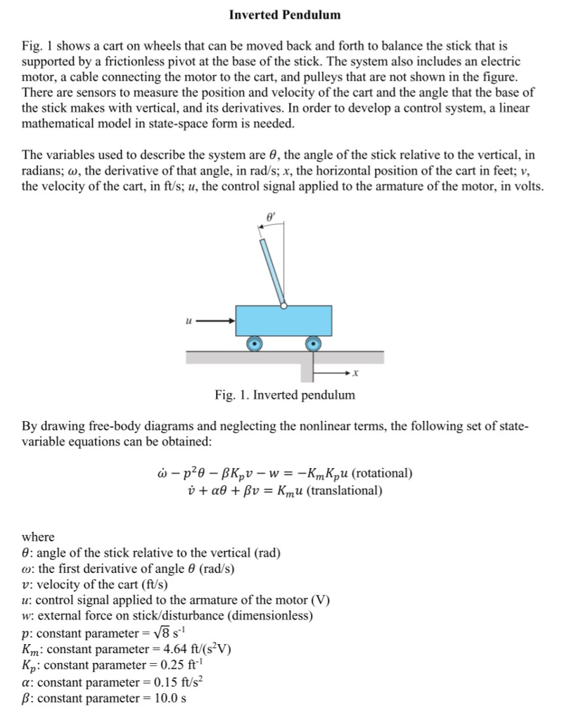
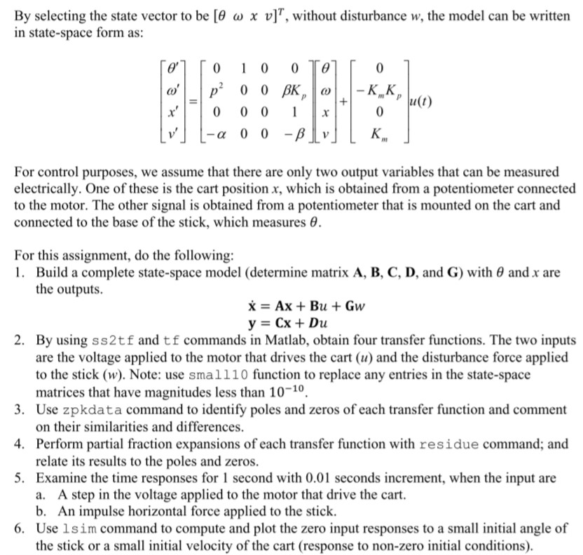
Inverted Pendulum Fig. 1 shows a cart on wheels that can be moved back and forth to balance the stick that is supported by a frictionless pivot at the base of the stick. The system also includes an electric motor, a cable connecting the motor to the cart, and pulleys that are not shown in the figure There are sensors to measure the position and velocity of the cart and the angle that the base of the stick makes with vertical, and its derivatives. In order to develop a control system, a linear mathematical model in state-space form is needed The variables used to describe the system are , the angle of the stick relative to the vertical, in radians; w, the derivative of that angle, in rad/s; x, the horizontal position of the cart in feet; v, the velocity of the cart, in ft/s; u, the control signal applied to the armature of the motor, in volts lu Fig. 1. Inverted pendulum By drawing free-body diagrams and neglecting the nonlinear terms, the following set of state variable equations can be obtained: a) _ p2 -BKpu-w--KmKpu (rotational) + + -K,nu (translational) where : angle of the stick relative to the vertical (rad) w: the first derivative of angle (rad/s) v: velocity of the cart (ft/s) u: control signal applied to the armature of the motor (V) w: external force on stick/disturbance (dimensionless) p: constant parameter V8 s1 Km: constant parameter 4.64 f/(s2V) Kp: constant parameter 0.25 ft a: constant parameter 0.15 ft/s B: constant parameter 10.0 s By selecting the state vector to be [0 w x v]r, without disturbance w, the model can be written in state-space form as: Km K , /, 111(1) 0 0 0x -a 0 0 For control purposes, we assume that there are only two output variables that can be measured electrically. One of these is the cart position x, which is obtained from a potentiometer connected to the motor. The other signal is obtained from a potentiometer that is mounted on the cart and connected to the base of the stick, which measures . For this assignment, do the following: l. Build a complete state-space model (determine matrix A. B, C, D, and G) with and x are the outputs. 2. By using ss2tf and tf commands in Matlab, obtain four transfer functions. The two inputs are the voltage applied to the motor that drives the cart (u) and the disturbance force applied to the stick (w) Note: use smalll0 function to replace any entries in the state-space matrices that have magnitudes less than 10-10. 3. Use zpkdata command to identify poles and zeros of each transfer function and comment 4. Perform partial fraction expansions of each transfer function with residue command; and 5. Examine the time responses for 1 second with 0.01 seconds increment, when the input are on their similarities and differences. relate its results to the poles and zeros. a. A step in the voltage applied to the motor that drive the cart. b. An impulse horizontal force applied to the stick. Use lsim command to compute and plot the zero input responses to a small initial angle of the stick or a small initial velocity of the cart (response to non-zero initial conditions). 6. Inverted Pendulum Fig. 1 shows a cart on wheels that can be moved back and forth to balance the stick that is supported by a frictionless pivot at the base of the stick. The system also includes an electric motor, a cable connecting the motor to the cart, and pulleys that are not shown in the figure There are sensors to measure the position and velocity of the cart and the angle that the base of the stick makes with vertical, and its derivatives. In order to develop a control system, a linear mathematical model in state-space form is needed The variables used to describe the system are , the angle of the stick relative to the vertical, in radians; w, the derivative of that angle, in rad/s; x, the horizontal position of the cart in feet; v, the velocity of the cart, in ft/s; u, the control signal applied to the armature of the motor, in volts lu Fig. 1. Inverted pendulum By drawing free-body diagrams and neglecting the nonlinear terms, the following set of state variable equations can be obtained: a) _ p2 -BKpu-w--KmKpu (rotational) + + -K,nu (translational) where : angle of the stick relative to the vertical (rad) w: the first derivative of angle (rad/s) v: velocity of the cart (ft/s) u: control signal applied to the armature of the motor (V) w: external force on stick/disturbance (dimensionless) p: constant parameter V8 s1 Km: constant parameter 4.64 f/(s2V) Kp: constant parameter 0.25 ft a: constant parameter 0.15 ft/s B: constant parameter 10.0 s By selecting the state vector to be [0 w x v]r, without disturbance w, the model can be written in state-space form as: Km K , /, 111(1) 0 0 0x -a 0 0 For control purposes, we assume that there are only two output variables that can be measured electrically. One of these is the cart position x, which is obtained from a potentiometer connected to the motor. The other signal is obtained from a potentiometer that is mounted on the cart and connected to the base of the stick, which measures . For this assignment, do the following: l. Build a complete state-space model (determine matrix A. B, C, D, and G) with and x are the outputs. 2. By using ss2tf and tf commands in Matlab, obtain four transfer functions. The two inputs are the voltage applied to the motor that drives the cart (u) and the disturbance force applied to the stick (w) Note: use smalll0 function to replace any entries in the state-space matrices that have magnitudes less than 10-10. 3. Use zpkdata command to identify poles and zeros of each transfer function and comment 4. Perform partial fraction expansions of each transfer function with residue command; and 5. Examine the time responses for 1 second with 0.01 seconds increment, when the input are on their similarities and differences. relate its results to the poles and zeros. a. A step in the voltage applied to the motor that drive the cart. b. An impulse horizontal force applied to the stick. Use lsim command to compute and plot the zero input responses to a small initial angle of the stick or a small initial velocity of the cart (response to non-zero initial conditions). 6
Step by Step Solution
There are 3 Steps involved in it

Get step-by-step solutions from verified subject matter experts


