Question
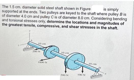
is simply The 1.5 cm. diameter solid steel shaft shown in Figure supported at the ends. Two pulleys are keyed to the shaft where

is simply The 1.5 cm. diameter solid steel shaft shown in Figure supported at the ends. Two pulleys are keyed to the shaft where pulley B is of diameter 4.0 cm and pulley C is of diameter 8.0 cm. Considering bending and torsional stresses only, determine the locations and magnitudes of the greatest tensile, compressive, and shear stresses in the shaft. 10 cm 200 N 1000 N 10 cm B&G 500 N 100 N 10 cm
Step by Step Solution
There are 3 Steps involved in it
Step: 1
Here are the steps to solve this problem 1 Find the bending moment at each section due to each force ...
Get Instant Access to Expert-Tailored Solutions
See step-by-step solutions with expert insights and AI powered tools for academic success
Step: 2

Step: 3

Ace Your Homework with AI
Get the answers you need in no time with our AI-driven, step-by-step assistance
Get StartedRecommended Textbook for
Shigleys Mechanical Engineering Design
Authors: Richard G. Budynas, J. Keith Nisbett
9th edition
77679520, 73529281, 1259986241, 978-0077679521, 9780073529288, 9781259986246, 978-1121345317
Students also viewed these Accounting questions
Question
Answered: 1 week ago
Question
Answered: 1 week ago
Question
Answered: 1 week ago
Question
Answered: 1 week ago
Question
Answered: 1 week ago
Question
Answered: 1 week ago
Question
Answered: 1 week ago
Question
Answered: 1 week ago
Question
Answered: 1 week ago
Question
Answered: 1 week ago
Question
Answered: 1 week ago
Question
Answered: 1 week ago
Question
Answered: 1 week ago
Question
Answered: 1 week ago
Question
Answered: 1 week ago
Question
Answered: 1 week ago
Question
Answered: 1 week ago
Question
Answered: 1 week ago
Question
Answered: 1 week ago
Question
Answered: 1 week ago
Question
Answered: 1 week ago
Question
Answered: 1 week ago
View Answer in SolutionInn App


