Answered step by step
Verified Expert Solution
Question
1 Approved Answer
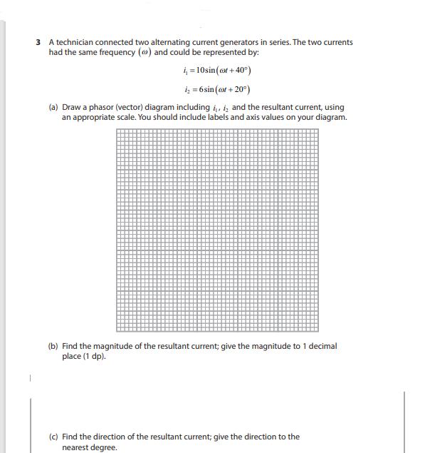
3 A technician connected two alternating current generators in series. The two currents had the same frequency () and could be represented by: i


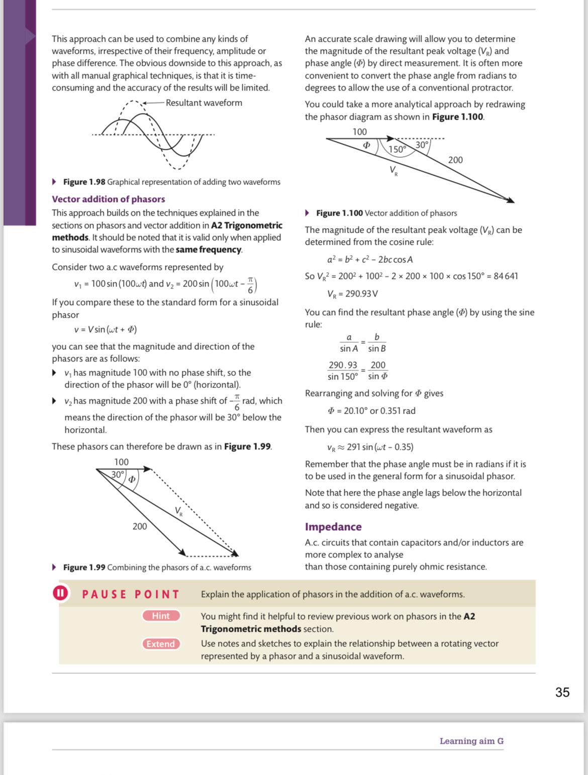
3 A technician connected two alternating current generators in series. The two currents had the same frequency () and could be represented by: i = 10sin(col +40) i = 6sin (@xx +20) (a) Draw a phasor (vector) diagram including , 2 and the resultant current, using an appropriate scale. You should include labels and axis values on your diagram. (b) Find the magnitude of the resultant current; give the magnitude to 1 decimal place (1 dp). (c) Find the direction of the resultant current; give the direction to the nearest degree. This approach can be used to combine any kinds of waveforms, irrespective of their frequency, amplitude or phase difference. The obvious downside to this approach, as with all manual graphical techniques, is that it is time- consuming and the accuracy of the results will be limited. Resultant waveform D Figure 1.98 Graphical representation of adding two waveforms Vector addition of phasors This approach builds on the techniques explained in the sections on phasors and vector addition in A2 Trigonometric methods. It should be noted that it is valid only when applied to sinusoidal waveforms with the same frequency. Consider two a.c waveforms represented by v = 100 sin (100wt) and v = 200 sin (100wt - Dowt - ) If you compare these to the standard form for a sinusoidal phasor v=Vsin (wt + D) you can see that the magnitude and direction of the phasors are as follows: v has magnitude 100 with no phase shift, so the direction of the phasor will be 0 (horizontal). v has magnitude 200 with a phase shift of rad, which 6 means the direction of the phasor will be 30 below the horizontal. These phasors can therefore be drawn as in Figure 1.99. 100 11 30 200 Figure 1.99 Combining the phasors of a.c. waveforms PAUSE POINT Hint Extend An accurate scale drawing will allow you to determine the magnitude of the resultant peak voltage (VR) and phase angle (0) by direct measurement. It is often more convenient to convert the phase angle from radians to degrees to allow the use of a conventional protractor. You could take a more analytical approach by redrawing the phasor diagram as shown in Figure 1.100. 100 a sin A Figure 1.100 Vector addition of phasors The magnitude of the resultant peak voltage (VR) can be determined from the cosine rule: 290.93 sin 150 a = b+ c-2bc cos A So V = 200 + 100 - 2x 200 x 100 x cos 150 = 84641 VR = 290.93V You can find the resultant phase angle (4) by using the sine rule: = 150 b sin B 30 200 sin 200 Rearranging and solving for gives 20.10 or 0.351 rad Then you can express the resultant waveform as VR 291 sin (wt - 0.35) Remember that the phase angle must be in radians if it is to be used in the general form for a sinusoidal phasor. Note that here the phase angle lags below the horizontal and so is considered negative. Impedance A.c. circuits that contain capacitors and/or inductors are more complex to analyse than those containing purely ohmic resistance. Explain the application of phasors in the addition of a.c. waveforms. You might find it helpful to review previous work on phasors in the A2 Trigonometric methods section. Use notes and sketches to explain the relationship between a rotating vector represented by a phasor and a sinusoidal waveform. Learning aim G 35
Step by Step Solution
There are 3 Steps involved in it
Step: 1

Get Instant Access to Expert-Tailored Solutions
See step-by-step solutions with expert insights and AI powered tools for academic success
Step: 2

Step: 3

Ace Your Homework with AI
Get the answers you need in no time with our AI-driven, step-by-step assistance
Get Started


