

Answered step by step
Verified Expert Solution
Question
1 Approved Answer
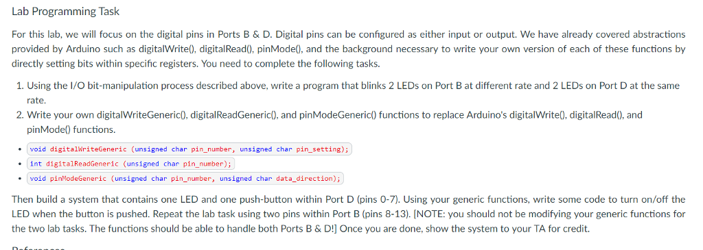
Lab Programming Task For this lab, we will focus on the digital pins in Ports B&D. Digital pins can be configured as either input or
Step by Step Solution
There are 3 Steps involved in it
Step: 1

Get Instant Access to Expert-Tailored Solutions
See step-by-step solutions with expert insights and AI powered tools for academic success
Step: 2

Step: 3
Ace Your Homework with AI
Get the answers you need in no time with our AI-driven, step-by-step assistance
Get Started
Implementing Ai And Machine Learning For Business Optimization
Authors: Robert K Wiley
1st Edition
B0CPQJW72N, 979-8870675855