Answered step by step
Verified Expert Solution
Question
1 Approved Answer
LABORATORY 2: DYNAMIC SYSTEM SIMULATION IN MATLAB / SIMULINK 1. OBJECTIVES Matlab Simulink is used for modeling and simulation of the systems. In Simulink, system
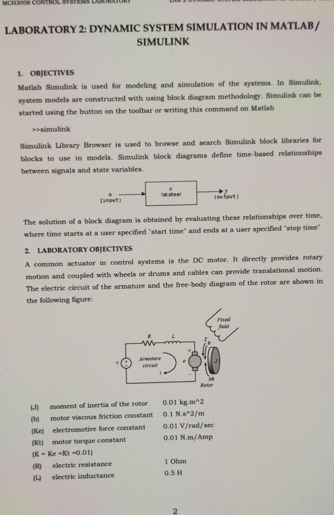
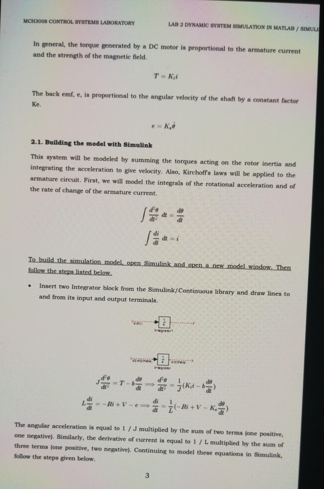
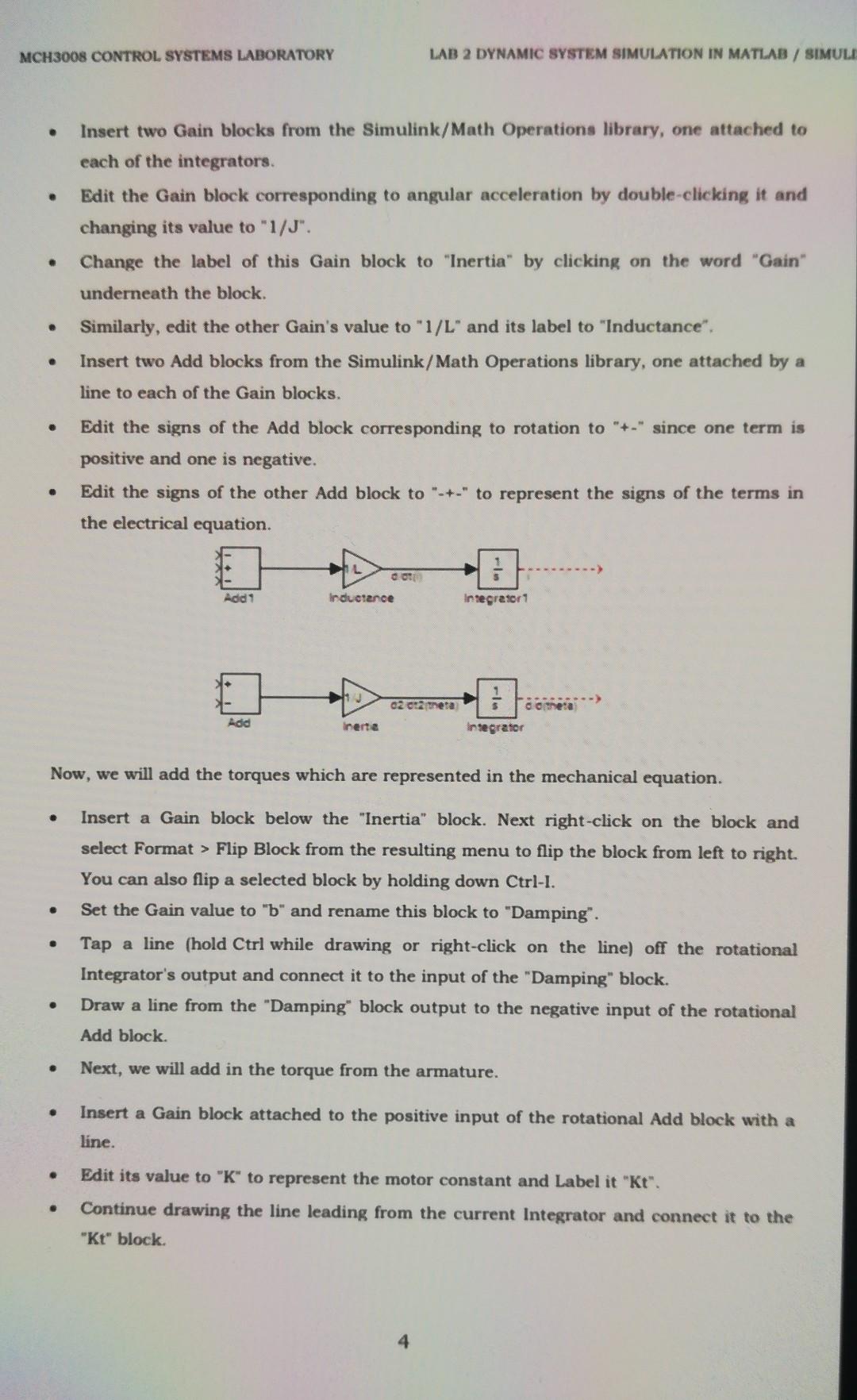
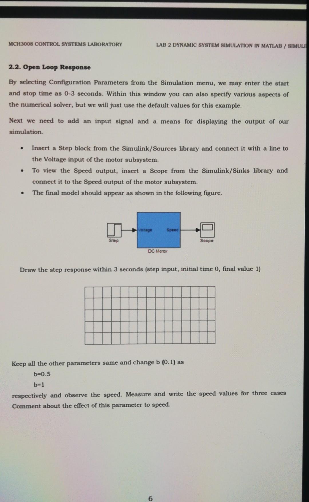
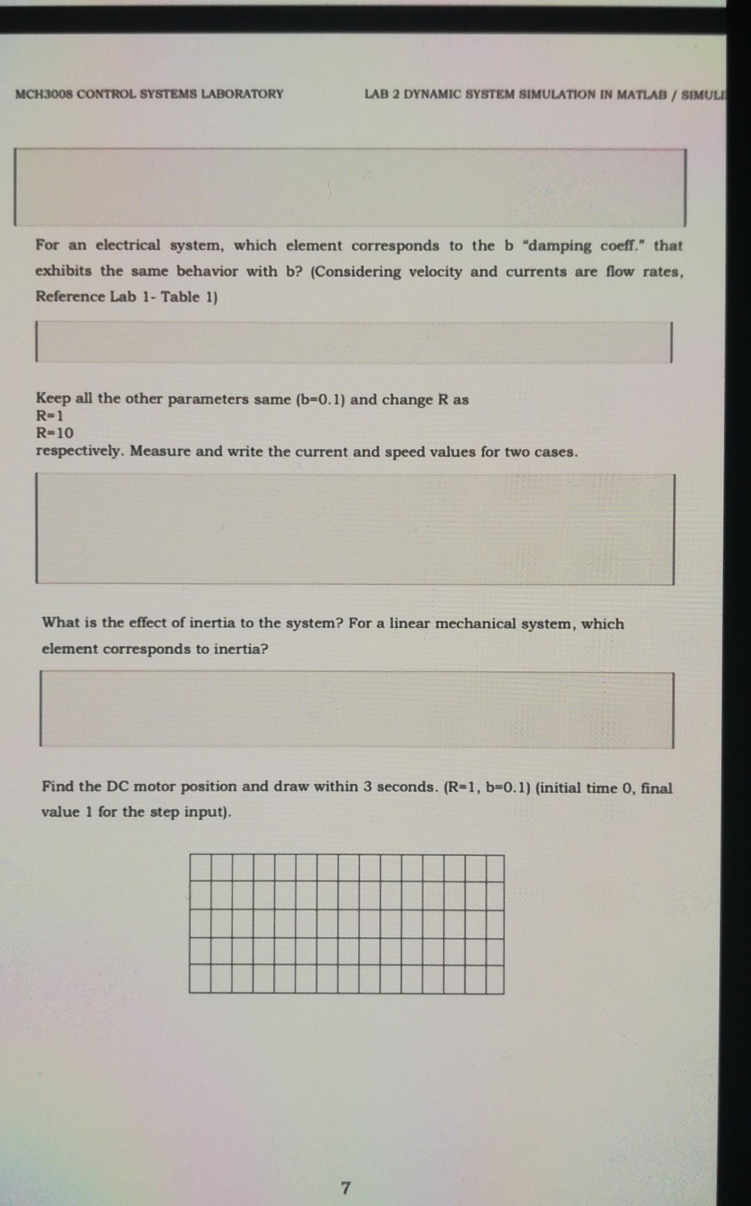
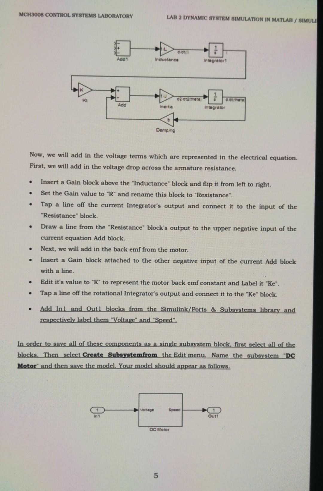
LABORATORY 2: DYNAMIC SYSTEM SIMULATION IN MATLAB / SIMULINK 1. OBJECTIVES Matlab Simulink is used for modeling and simulation of the systems. In Simulink, system models are constructed with using block diagram methodology. Simulink can be started using the button on the toolbar or writing this command on Matlab >ssimulink Simulink Library Browser is used to browse and search Simulink block libraries for blocks to use in models. Simulink block diagrams define time-based relationships between signals and state variables. The solution of a block diagram is obtained by evaluating these relationships over time, where time starts at a user specified "start time" and ends at a user specified "stop time" 2. LABORATORY OBJECTIVES A common actuator in control systems is the DC motor. It directly provides rotary motion and coupled with wheels or drums and cables can provide translational motion. The electric circuit of the armature and the free-body diagram of the rotor are shown in the following figure: (J) moment of inertia of the rotor 0.01kgm2 (b) motor viscous friction constant 0.1N.s2/m (Ke) electromotive force constant 0.01V/rad/sec (Kt) motor torque constant 0.01 N.m/Amp (K=Ke=Kt=0.01) (R) electric resistance 1Ohm (L) electric inductance 0.5H In general, the torque generated by a DC motor is proportional to the armature current and the strength of the magnetic field. T=K1i The back emf, e, is proportional to the angular velocity of the shaft by a constant factor Ke. e=Ke 2.1. Building the model with Simulink This system will be modeled by summing the torques acting on the rotor inertia and integrating the acceleration to give velocity. Also, Kirchoff s laws will be applied to the armature circuit. First, we will model the integrals of the rotational acceleration and of the rate of change of the armature current. dt2d2dt=dtddtdidt=i To build the simulation model, open Simulink and open a new model window. Then follow the steps listed below. - Insert two Integrator block from the Simulink/Continuous library and draw lines to and from its input and output terminals. Jdt2d2=Tbdtddt2d2=J1(Ktibdtd)Ldtdi=Ri+Vedtdi=L1(Ri+VKedtd) The angular acceleration is equal to 1/J multiplied by the sum of two terms (one positive, one negative). Similarly, the derivative of current is equal to 1 / L multiplied by the sum of three terms (one positive, two negative). Continuing to model these equations in Simulink, follow the steps given below. MCH3008 CONTROL, SYSTEMS LABORATORY LAB 2 DYNAMIC SYSTEM SIMULATION IN MATLAB / SIMU - Insert two Gain blocks from the Simulink/Math Operations library, one attached to each of the integrators. - Edit the Gain block corresponding to angular acceleration by double-clicking it and changing its value to " 1/J ". - Change the label of this Gain block to "Inertia" by clicking on the word "Gain" underneath the block. - Similarly, edit the other Gain's value to "1/L" and its label to "Inductance". - Insert two Add blocks from the Simulink/Math Operations library, one attached by a line to each of the Gain blocks. - Edit the signs of the Add block corresponding to rotation to "+-" since one term is positive and one is negative. - Edit the signs of the other Add block to ".+-" to represent the signs of the terms in the electrical equation. Now, we will add the torques which are represented in the mechanical equation. - Insert a Gain block below the "Inertia" block. Next right-click on the block and select Format > Flip Block from the resulting menu to flip the block from left to right. You can also flip a selected block by holding down Ctrl-I. - Set the Gain value to "b" and rename this block to "Damping". - Tap a line (hold Ctrl while drawing or right-click on the line) off the rotational Integrator's output and connect it to the input of the "Damping" block. - Draw a line from the "Damping" block output to the negative input of the rotational Add block. - Next, we will add in the torque from the armature. - Insert a Gain block attached to the positive input of the rotational Add block with a line. - Edit its value to " K " to represent the motor constant and Label it "Kt". - Continue drawing the line leading from the current Integrator and connect it to the "Kt" block. 2.2. Open Loop Response By selecting Configuration Parameters from the Simulation menu, we may enter the start and stop time as 03 seconds. Within this window you can also specify various aspects of the numerical solver, but we will just use the default values for this example. Next we need to add an input signal and a means for displaying the output of our simulation. - Insert a Step block from the Simulink/Sources library and connect it with a line to the Voltage input of the motor subsystem. - To view the Speed output, insert a Scope from the Simulink/Sinks library and connect it to the Speed output of the motor subsystem. - The final model should appear as shown in the following figure. Draw the step response within 3 seconds (step input, initial time 0 , final value 1) Keep all the other parameters same and change b(0.1) as b=0.5b=1 respectively and observe the speed. Measure and write the speed values for three cases Comment about the effect of this parameter to speed. For an electrical system, which element corresponds to the b "damping coeff." that exhibits the same behavior with b? (Considering velocity and currents are flow rates, Reference Lab 1- Table 1) Keep all the other parameters same (b=0.1) and change R as R=1 R=10 respectively. Measure and write the current and speed values for two cases. What is the effect of inertia to the system? For a linear mechanical system, which element corresponds to inertia? Find the DC motor position and draw within 3 seconds. (R=1,b=0.1) (initial time 0 , final value 1 for the step input). MCH3008 CONTROL SYSTEMS LABORATORY LAB 2 DYNAMIC SYSTEM SIMULATION IN MATLAB / SIMULI Now, we will add in the voltage terms which are represented in the electrical equation. First, we will add in the voltage drop across the armature resistance. - Insert a Gain block above the "Inductance" block and flip it from left to right. - Set the Gain value to " R " and rename this block to "Resistance". - Tap a line off the current Integrator's output and connect it to the input of the "Resistance" block. - Draw a line from the "Resistance" block's output to the upper negative input of the current equation Add block. - Next, we will add in the back emf from the motor. - Insert a Gain block attached to the other negative input of the current Add block with a line. - Edit it's value to "K" to represent the motor back emf constant and Label it "Ke". - Tap a line off the rotational Integrator's output and connect it to the "Ke" block. - Add Inl and Outl blocks from the Simulink/Ports \& Subsystems library and respectively label them "Voltage" and "Speed". In order to save all of these components as a single subsystem block, first select all of the blocks. Then select Create Subsystemfrom the Edit menu. Name the subsystem "DC Motor" and then save the model. Your model should appear as follows
Step by Step Solution
There are 3 Steps involved in it
Step: 1

Get Instant Access to Expert-Tailored Solutions
See step-by-step solutions with expert insights and AI powered tools for academic success
Step: 2

Step: 3

Ace Your Homework with AI
Get the answers you need in no time with our AI-driven, step-by-step assistance
Get Started


