Answered step by step
Verified Expert Solution
Question
1 Approved Answer
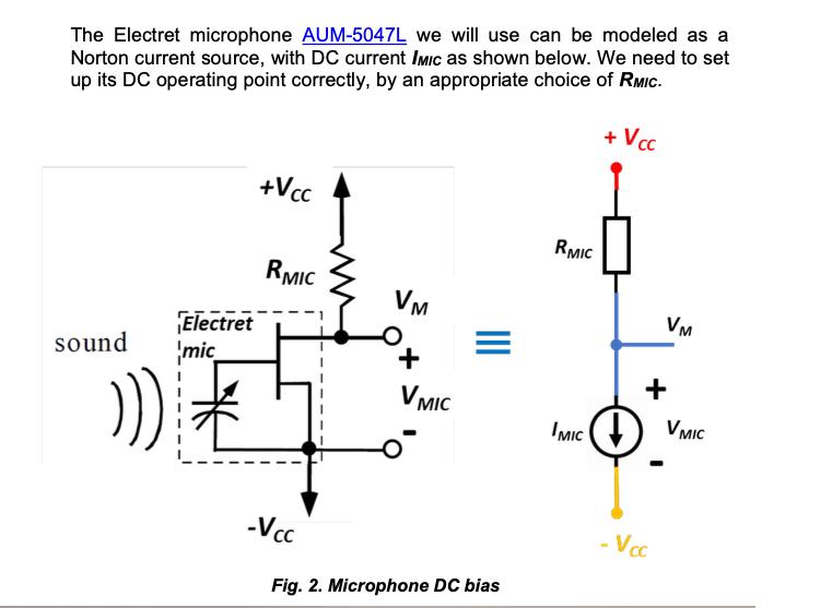
The Electret microphone AUM-5047L we will use can be modeled as a Norton current source, with DC current IMIC as shown below. We need


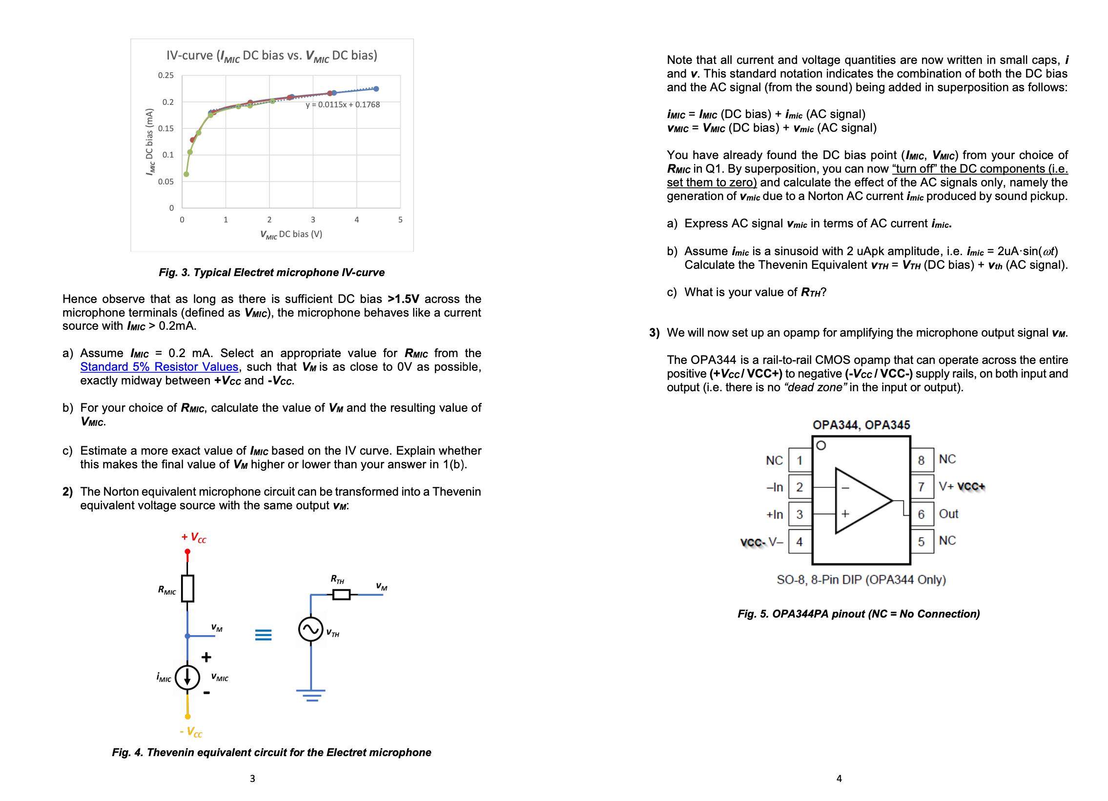
The Electret microphone AUM-5047L we will use can be modeled as a Norton current source, with DC current IMIC as shown below. We need to set up its DC operating point correctly, by an appropriate choice of RMIC. + Vcc sound ))) Electret mic +Vcc RMIC -Vcc VM + V MIC Fig. 2. Microphone DC bias RMIC MIC) VM + - Vcc V MIC MIC DC bias (mA) IV-curve (MIC DC bias vs. V MIC DC bias) 0.25 0.2 0.15 0.1 0.05 0 0 RMIC Fig. 3. Typical Electret microphone IV-curve Hence observe that as long as there is sufficient DC bias >1.5V across the microphone terminals (defined as VMIC), the microphone behaves like a current source with IMIC > 0.2mA. MIC 1 a) Assume IMIC = 0.2 mA. Select an appropriate value for RMIC from the Standard 5% Resistor Values, such that VM is as close to OV as possible, exactly midway between +Vcc and -Vcc. b) For your choice of RMIC, calculate the value of VM and the resulting value of VMIC. + Vcc c) Estimate a more exact value of IMIC based on the IV curve. Explain whether this makes the final value of VM higher or lower than your answer in 1(b). y = 0.0115x + 0.1768 2) The Norton equivalent microphone circuit can be transformed into a Thevenin equivalent voltage source with the same output VM: VM + .Vcc 2 3 VMIC DC bias (V) V MIC 4 3 5 RTH VTH VM Fig. 4. Thevenin equivalent circuit for the Electret microphone Note that all current and voltage quantities are now written in small caps, i and v. This standard notation indicates the combination of both the DC bias and the AC signal (from the sound) being added in superposition as follows: MIC = IMIC (DC bias) + imic (AC signal) VMIC = VMIC (DC bias) + Vmic (AC signal) You have already found the DC bias point (IMIC, VMIC) from your choice of RMIC in Q1. By superposition, you can now "turn off" the DC components (i.e. set them to zero) and calculate the effect of the AC signals only, namely the generation of Vmic due to a Norton AC current imic produced by sound pickup. a) Express AC signal Vmic in terms of AC current mic. b) Assume imic is a sinusoid with 2 uApk amplitude, i.e. mic = 2uA.sin(at) Calculate the Thevenin Equivalent VTH = VTH (DC bias) + Vth (AC signal). c) What is your value of RTH? 3) We will now set up an opamp for amplifying the microphone output signal VM. The OPA344 is a rail-to-rail CMOS opamp that can operate across the entire positive (+Vcc/VCC+) to negative (-Vcc/VCC-) supply rails, on both input and output (i.e. there is no "dead zone" in the input or output). NC 1 -In 2 +In 3 VCC-V- 4 OPA344, OPA345 + 8 7 6 5 NC V+ VCC+ Out NC SO-8, 8-Pin DIP (OPA344 Only) Fig. 5. OPA344PA pinout (NC = No Connection)
Step by Step Solution
★★★★★
3.31 Rating (160 Votes )
There are 3 Steps involved in it
Step: 1

Get Instant Access to Expert-Tailored Solutions
See step-by-step solutions with expert insights and AI powered tools for academic success
Step: 2

Step: 3

Ace Your Homework with AI
Get the answers you need in no time with our AI-driven, step-by-step assistance
Get Started


