

Question: LB GND Vec CA 1 6 2 14 BA IO EN 11 I_2 yl I_3 1 1 0 7 CA 0 f IK DIL 1
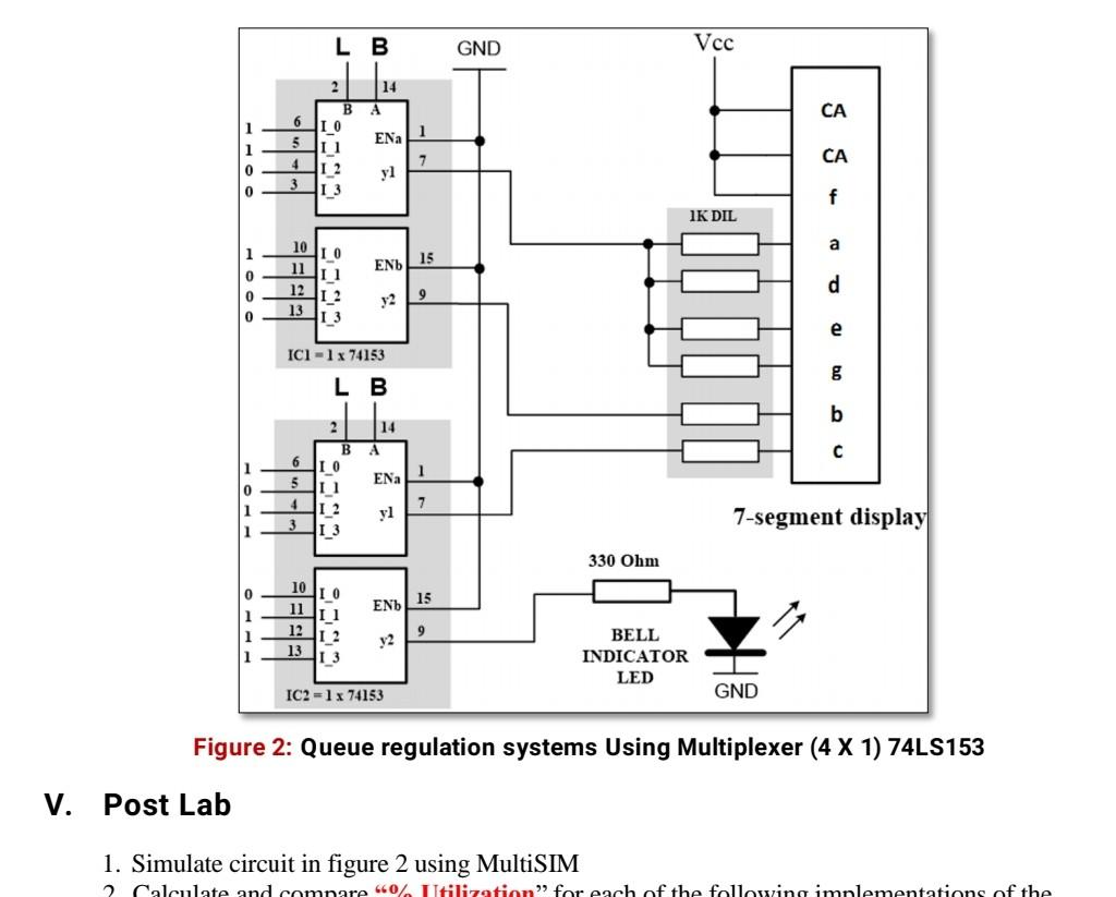
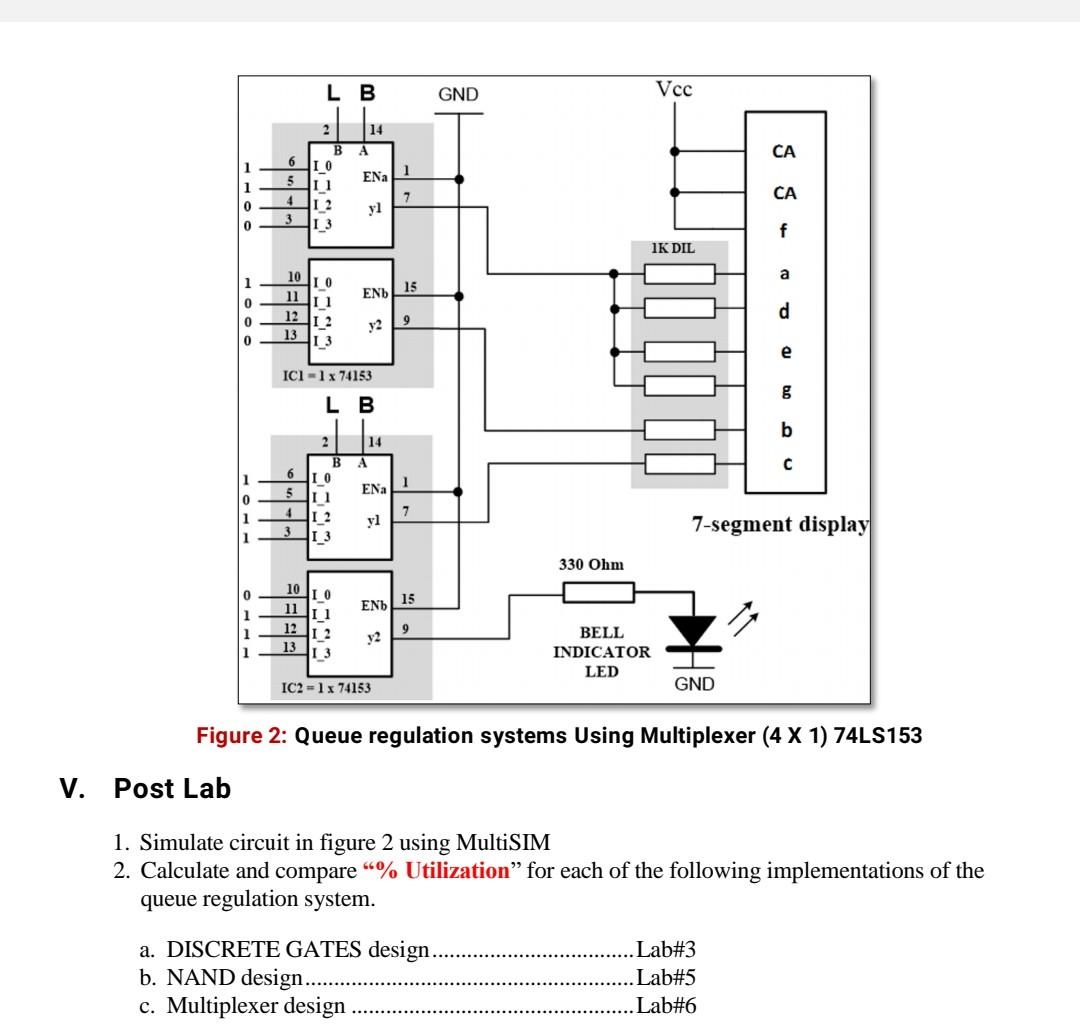
LB GND Vec CA 1 6 2 14 BA IO EN 11 I_2 yl I_3 1 1 0 7 CA 0 f IK DIL 1 a 15 END 10 11 12 13 0 0 0 I 0 I 1 2 I 3 d y2 9 e ICI - 1 x 74153 8 LB b 14 1 0 1 1 6 5 4 2 B I 0 1 I_2 I_3 EN 7 7-segment display 330 Ohm 15 EN 0 1 1 1 10 I 0 11 N1 12 1 2 13 I 3 9 y2 BELL INDICATOR LED IC2 -1x 74153 GND Figure 2: Queue regulation systems Using Multiplexer (4 X 1) 74LS153 V. Post Lab 1. Simulate circuit in figure 2 using MultiSIM Calculate and compare 40% Utilization for each of the following implementations of the LB GND Vcc A CA 6 5 EN 1 B 10 11 I_2 I 3 7 1 0 0 CA yl f IK DIL a EN 15 1 0 0 0 10 11 12 13 10 11 L2 I_3 d y2 9 e ICI - 1x74153 LB b 1 6 5 4 2 14 B A IO I 1 EN I 2 yl I_3 7 7-segment display 1 330 Ohm 0 EN) 15 1 1 1 10 0 11 1 12 1 2 13 I 3 9 y2 BELL INDICATOR LED IC2 -1x 74153 GND Figure 2: Queue regulation systems Using Multiplexer (4 X 1) 74LS153 V. Post Lab 1. Simulate circuit in figure 2 using MultiSIM 2. Calculate and compare % Utilization for each of the following implementations of the queue regulation system. a. DISCRETE GATES design b. NAND design.. c. Multiplexer design . Lab#3 .Lab#5 .Lab#6 LB GND Vec CA 1 6 2 14 BA IO EN 11 I_2 yl I_3 1 1 0 7 CA 0 f IK DIL 1 a 15 END 10 11 12 13 0 0 0 I 0 I 1 2 I 3 d y2 9 e ICI - 1 x 74153 8 LB b 14 1 0 1 1 6 5 4 2 B I 0 1 I_2 I_3 EN 7 7-segment display 330 Ohm 15 EN 0 1 1 1 10 I 0 11 N1 12 1 2 13 I 3 9 y2 BELL INDICATOR LED IC2 -1x 74153 GND Figure 2: Queue regulation systems Using Multiplexer (4 X 1) 74LS153 V. Post Lab 1. Simulate circuit in figure 2 using MultiSIM Calculate and compare 40% Utilization for each of the following implementations of the LB GND Vcc A CA 6 5 EN 1 B 10 11 I_2 I 3 7 1 0 0 CA yl f IK DIL a EN 15 1 0 0 0 10 11 12 13 10 11 L2 I_3 d y2 9 e ICI - 1x74153 LB b 1 6 5 4 2 14 B A IO I 1 EN I 2 yl I_3 7 7-segment display 1 330 Ohm 0 EN) 15 1 1 1 10 0 11 1 12 1 2 13 I 3 9 y2 BELL INDICATOR LED IC2 -1x 74153 GND Figure 2: Queue regulation systems Using Multiplexer (4 X 1) 74LS153 V. Post Lab 1. Simulate circuit in figure 2 using MultiSIM 2. Calculate and compare % Utilization for each of the following implementations of the queue regulation system. a. DISCRETE GATES design b. NAND design.. c. Multiplexer design . Lab#3 .Lab#5 .Lab#6
Step by Step Solution
There are 3 Steps involved in it

Get step-by-step solutions from verified subject matter experts