

Answered step by step
Verified Expert Solution
Question
1 Approved Answer
Looking for worked solutions to part 2, 3 and 4. Answers are attached Q. 1 The frame structure ABCDE shown in Figure Q. 1 represents
Looking for worked solutions to part 2, 3 and 4. 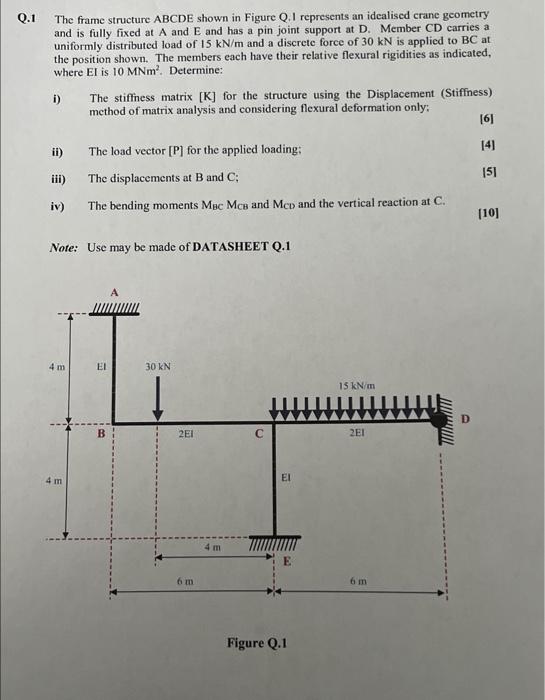
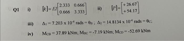
Q. 1 The frame structure ABCDE shown in Figure Q. 1 represents an idealised crane geometry and is fully fixed at A and E and has a pin joint support at D. Member CD carries a uniformly distributed load of 15kN/m and a discrete force of 30kN is applied to BC at the position shown. The members each have their relative flexural rigidities as indicated, where EI is 10MNm2. Determine: i) The stiffness matrix [K] for the structure using the Displacement (Stiffness) method of matrix analysis and considering flexural deformation only: [6] ii) The load vector [P] for the applied loading; [4] iii) The displacements at B and C; [5] iv) The bending moments MBCMCB and MCD and the vertical reaction at C. [10] Note: Use may be made of DATASHEET Q. 1 Figure Q. 1 i) [k]=EI[2.3330.6660.6663.333] ii) [P]=[+26.67+54.17] iii) 1=7.203104rads=B;2=14.8134104rads=c; iv) MCB=37.89kNm;MBC=7.19kNm;MCD=52.69kNm Answers are attached
Step by Step Solution
There are 3 Steps involved in it
Step: 1

Get Instant Access to Expert-Tailored Solutions
See step-by-step solutions with expert insights and AI powered tools for academic success
Step: 2

Step: 3
Ace Your Homework with AI
Get the answers you need in no time with our AI-driven, step-by-step assistance
Get Started
Vector Mechanics for Engineers Statics and Dynamics
Authors: Ferdinand Beer, E. Russell Johnston, Jr., Elliot Eisenberg, William Clausen, David Mazurek, Phillip Cornwell
8th Edition
73212229, 978-0073212227