Answered step by step
Verified Expert Solution
Question
1 Approved Answer
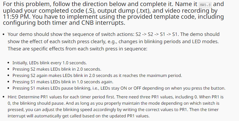
MODIFICATIONS TO MAKE: You must change this program so that: - Initially, the LEDs blink simultaneously every 1 . 0 seconds. - Pressing switches will
MODIFICATIONS TO MAKE:
You must change this program so that:
Initially, the LEDs blink simultaneously every seconds.
Pressing switches will change the timer period by seconds, either faster by pressing S or slower by pressing S
Given the timer configuration and seconds of the adjustment period, there are only three modes: second period ie pause second period, and second period.
Including xch allows use of SFR names, bit masks, etc.
#include
Interrupt vector setup
globl vectordispatch ## Port B change notification vector #
section vector code, keep
align
set nomips
ent vectordispatch
vectordispatch:
j isrvector ## Jump to actual ISR code, which is in text section
nop
end vectordispatch
size vectordispatchvectordispatch
globl vectordispatch ## Timer interrupt vector #
section vector code, keep
align
set nomips
ent vectordispatch
vectordispatch:
j isrvector ## Jump to actual ISR code, which is in text section
nop
end vectordispatch
size vectordispatchvectordispatch
Start of text section
text ## Text section contains code
set noreorder ## Disable instruction reordering
globl main ## Define main label as a global entity
ent main ## and an entry point
main:
Configure port A for output
sw zero, TRISA ## TRISA all PORTA bits output
sw zero, ANSELA ## ANSELA all PORTA bits digital
li tPORTBRBMASK
ori t tPORTBRBMASK
sw t TRISB ## TRISB x pins & inputs
sw zero, ANSELB ## ANSELB all PORTB bits digital
sw zero, TRISC ## TRISC all PORTC bits output
sw zero, ANSELC ## ANSELC all PORTC bits digital
Configure Timer
sw zero, TCON ## Clear TCONdisables timer to allow setup
The desired initial delay is sec between interrupts
ADD TIMER SETTINGS PRESCALE and PR TO GET THE DESIRED DELAY
Configure interrupts
lui tx
ori t tINTCONMVECMASK
sw t INTCON
li tIPCTIPMASK
sw t IPC
li tIPCCNBIPMASK
sw t IPCSET
li tIFSTIFMASK
sw t IEC
li tIECCNBIEMASK
sw t IECSET
add t t zero
or t t t
sw t CNENB
sw zero, CNENB
li tCNCONBONMASK
ori t tCNCONBCNSTYLEMASK
sw t CNCONB
ei
li tTCONTONMASK
sw t TCONSET
Main loop: doing nothing, just waiting for an interrupt
mainloop:
j mainloop
nop
end main
Delay loop for switch debouncing
global delay
ent delay
delay:
li txA
loop:
addi t t ## Decrement counter
bne t zero, loop ## and continue doing that until we hit
nop
jr ra
nop
end delay
global isrvector
ent isrvector
isrvector:
li tPORTBRBMASK
li tPORTBRBMASK
Check S
lw t CNFB
and t t t
beq t zero, checkS
nop
S pressedclear flag, then debounce and toggle if actually pressed
sw t CNFBCLR
jal delay
nop
lw t PORTB
and t t t
bne t zero, checkS
nop
ADD routine when a new S press
Check S
checkS:
and t t t
beq t zero, intdone
nop
S pressedclear flag, then debounce and toggle if actually pressed
sw t CNFBCLR
jal delay
nop
lw t PORTB
and t t t
bne t zero, intdone
nop
ADD routine when a new S press
intdone:
li tIFSCNBIFMASK ## Clear Port B change notification flag
sw t IFSCLR ## in IFS
eret ## Return from interrupt
end isrvector
global isrvector
ent isrvector
isrvector:
li tIFSTIFMASK
sw t IFSCLR
modify BEHAVIOR TO IMPLEMENT THE LED STATES DESCRIBED ABOVE
li tPORTARAMASK
li tPORTCRCMASK
intdone:
eret
end isrvector

Step by Step Solution
There are 3 Steps involved in it
Step: 1

Get Instant Access to Expert-Tailored Solutions
See step-by-step solutions with expert insights and AI powered tools for academic success
Step: 2

Step: 3

Ace Your Homework with AI
Get the answers you need in no time with our AI-driven, step-by-step assistance
Get Started


