Answered step by step
Verified Expert Solution
Question
1 Approved Answer
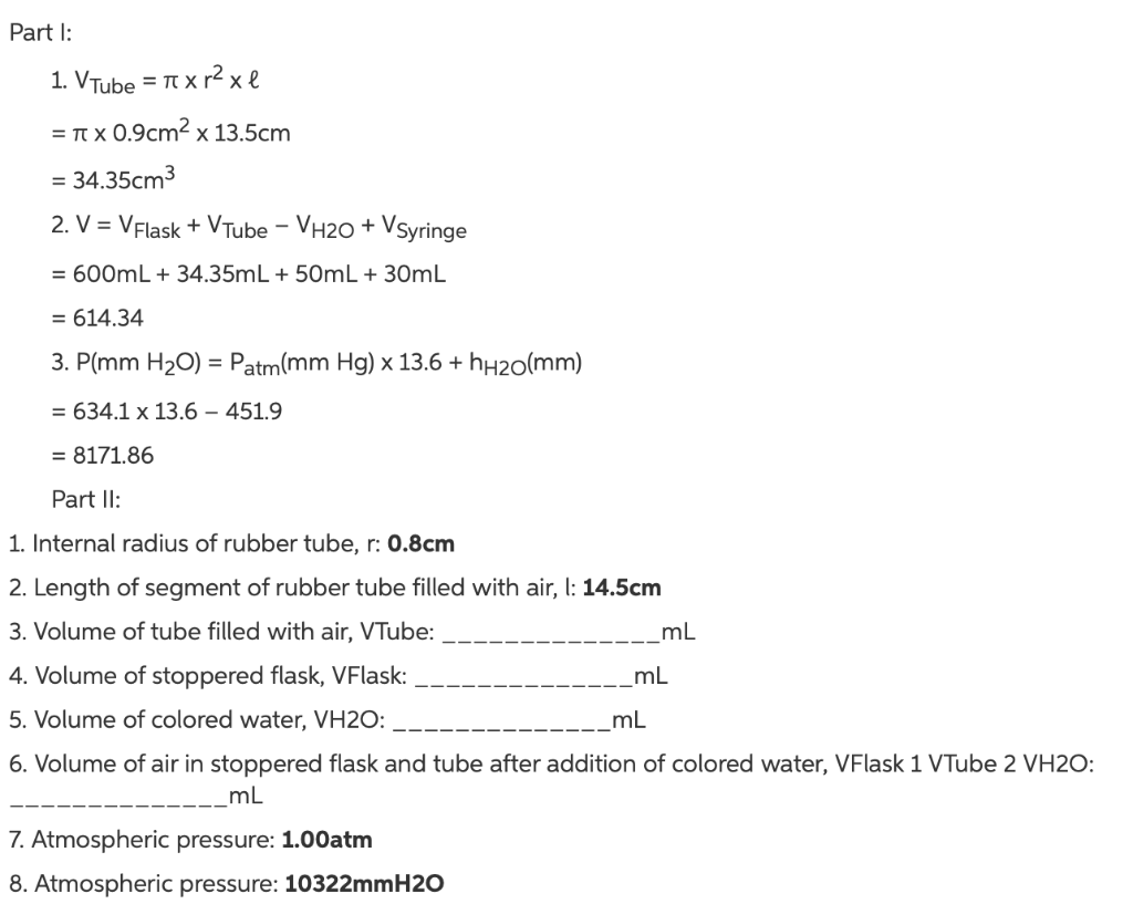
Part I: = xr x l 1. VTube = TV X = x 0.9cm x 13.5cm = 34.35cm 2. V = VFlask + VTube


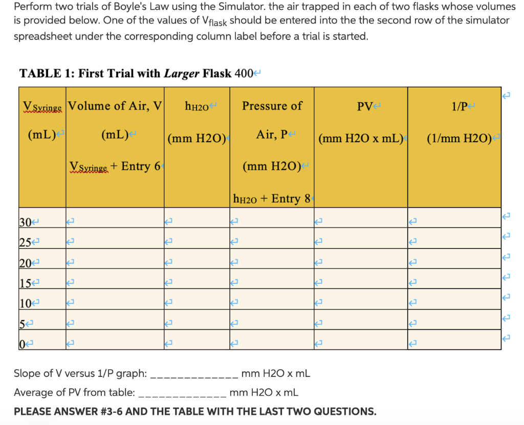
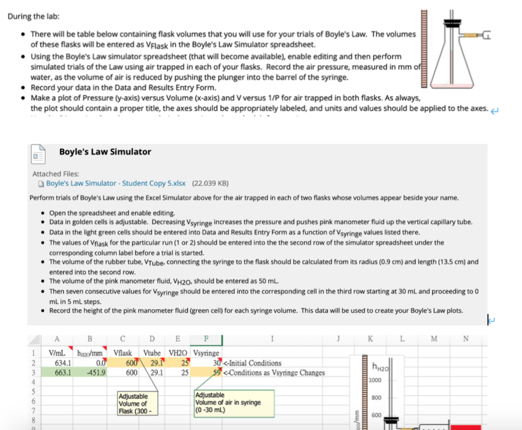
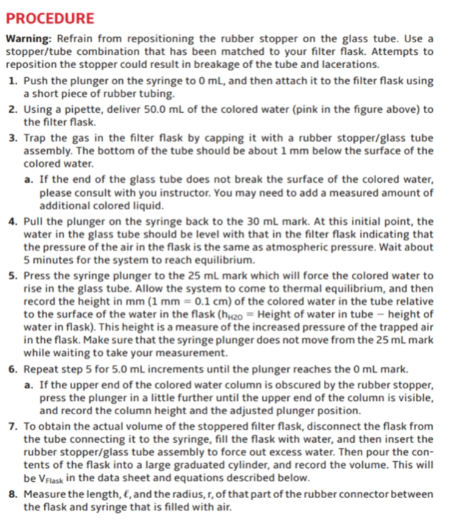
Part I: = xr x l 1. VTube = TV X = x 0.9cm x 13.5cm = 34.35cm 2. V = VFlask + VTube - VH2O + VSyringe = 600mL + 34.35mL + 50mL + 30mL = 614.34 3. P(mm HO) = Patm(mm Hg) x 13.6 +h+0(mm) = 634.1 x 13.6 - 451.9 = 8171.86 Part II: 1. Internal radius of rubber tube, r: 0.8cm 2. Length of segment of rubber tube filled with air, l: 14.5cm 3. Volume of tube filled with air, VTube: 4. Volume of stoppered flask, VFlask: 5. Volume of colored water, VH2O: mL 7. Atmospheric pressure: 1.00atm 8. Atmospheric pressure: 10322mmH2O mL mL 6. Volume of air in stoppered flask and tube after addition of colored water, VFlask 1 VTube 2 VH2O: mL Perform two trials of Boyle's Law using the Simulator. the air trapped in each of two flasks whose volumes is provided below. One of the values of Vflask should be entered into the the second row of the simulator spreadsheet under the corresponding column label before a trial is started. TABLE 1: First Trial with Larger Flask 400 VSyringe Volume of Air, V (mL) (mL) < VSyringe + Entry 6 30 25 20 15 10 5 0 2 2 2 k 2 (mm H2O) 2 2 k K h0 2 Pressure of Air, P (mm H2O) hHO + Entry 8 mm H2O x mL (mm H2O x mL) 2 J PV4 2 Slope of V versus 1/P graph: Average of PV from table: mm H2O x mL PLEASE ANSWER #3-6 AND THE TABLE WITH THE LAST TWO QUESTIONS. 2 2 2 2 2 1/P (1/mm H2O) 2] 2 2 2 During the lab: There will be table below containing flask volumes that you will use for your trials of Boyle's Law. The volumes of these flasks will be entered as VFlask in the Boyle's Law Simulator spreadsheet. Using the Boyle's Law simulator spreadsheet (that will become available), enable editing and then perform simulated trials of the Law using air trapped in each of your flasks. Record the air pressure, measured in mm of water, as the volume of air is reduced by pushing the plunger into the barrel of the syringe. Record your data in the Data and Results Entry Form. Make a plot of Pressure (y-axis) versus Volume (x-axis) and V versus 1/P for air trapped in both flasks. As always, the plot should contain a proper title, the axes should be appropriately labeled, and units and values should be applied to the axes. O Boyle's Law Simulator Attached Files: Boyle's Law Simulator - Student Copy 5.xlsx (22.039 KB) Perform trials of Boyle's Law using the Excel Simulator above for the air trapped in each of two flasks whose volumes appear beside your name. Open the spreadsheet and enable editing. Data in golden cells is adjustable. Decreasing Vsyringe increases the pressure and pushes pink manometer fluid up the vertical capillary tube. 7 8 Data in the light green cells should be entered into Data and Results Entry Form as a function of Vsyringe values listed there. The values of Vflask for the particular run (1 or 2) should be entered into the the second row of the simulator spreadsheet under the corresponding column label before a trial is started. The volume of the rubber tube, VTube, connecting the syringe to the flask should be calculated from its radius (0.9 cm) and length (13.5 cm) and entered into the second row. The volume of the pink manometer fluid, VH20, should be entered as 50 mL. Then seven consecutive values for Vsyringe should be entered into the corresponding cell in the third row starting at 30 mL and proceeding to 0 mL in 5 mL steps. Record the height of the pink manometer fluid (green cell) for each syringe volume. This data will be used to create your Boyle's Law plots. A B 1 V/mL hu/mm 2 3 4 5 6 634.1 663.1 0.0 -451.9 D E F C Vflask Vtube VH20 Vsyringe 600 29.1 25 600 29.1 25 Adjustable Volume of Flask (300- I 30 PROCEDURE Warning: Refrain from repositioning the rubber stopper on the glass tube. Use a stopper/tube combination that has been matched to your filter flask. Attempts to reposition the stopper could result in breakage of the tube and lacerations. 1. Push the plunger on the syringe to 0 mL, and then attach it to the filter flask using a short piece of rubber tubing. 2. Using a pipette, deliver 50.0 mL of the colored water (pink in the figure above) to the filter flask. 3. Trap the gas in the filter flask by capping it with a rubber stopper/glass tube assembly. The bottom of the tube should be about 1 mm below the surface of the colored water. a. If the end of the glass tube does not break the surface of the colored water, please consult with you instructor. You may need to add a measured amount of additional colored liquid. 4. Pull the plunger on the syringe back to the 30 mL mark. At this initial point, the water in the glass tube should be level with that in the filter flask indicating that the pressure of the air in the flask is the same as atmospheric pressure. Wait about 5 minutes for the system to reach equilibrium. 5. Press the syringe plunger to the 25 mL mark which will force the colored water to rise in the glass tube. Allow the system to come to thermal equilibrium, and then record the height in mm (1 mm = 0.1 cm) of the colored water in the tube relative to the surface of the water in the flask (hH20 = Height of water in tube - height of water in flask). This height is a measure of the increased pressure of the trapped air in the flask. Make sure that the syringe plunger does not move from the 25 mL mark while waiting to take your measurement. 6. Repeat step 5 for 5.0 mL increments until the plunger reaches the 0 mL mark. a. If the upper end of the colored water column is obscured by the rubber stopper, press the plunger in a little further until the upper end of the column is visible, and record the column height and the adjusted plunger position. 7. To obtain the actual volume of the stoppered filter flask, disconnect the flask from the tube connecting it to the syringe, fill the flask with water, and then insert the rubber stopper/glass tube assembly to force out excess water. Then pour the con- tents of the flask into a large graduated cylinder, and record the volume. This will be VFlask in the data sheet and equations described below. 8. Measure the length, &, and the radius, r, of that part of the rubber connector between the flask and syringe that is filled with air.
Step by Step Solution
★★★★★
3.34 Rating (154 Votes )
There are 3 Steps involved in it
Step: 1
Answer Vtube pir2l pi0913534...
Get Instant Access to Expert-Tailored Solutions
See step-by-step solutions with expert insights and AI powered tools for academic success
Step: 2

Step: 3

Ace Your Homework with AI
Get the answers you need in no time with our AI-driven, step-by-step assistance
Get Started


