Answered step by step
Verified Expert Solution
Question
1 Approved Answer
multirow[t]{2}{*}{ Operation } & multicolumn{8}{|c|}{ a input to the adder } & multicolumn{8}{|c|}{ b input to the adder } & multirow{2}{*}{C0} hline & A7
\multirow[t]{2}{*}{ Operation } & \multicolumn{8}{|c|}{ a input to the adder } & \multicolumn{8}{|c|}{ b input to the adder } & \multirow{2}{*}{C0} \\ \hline & A7 & A6 & A5 & A4 & A3 & A2 & A1 & A0 & B7 & B6 & B5


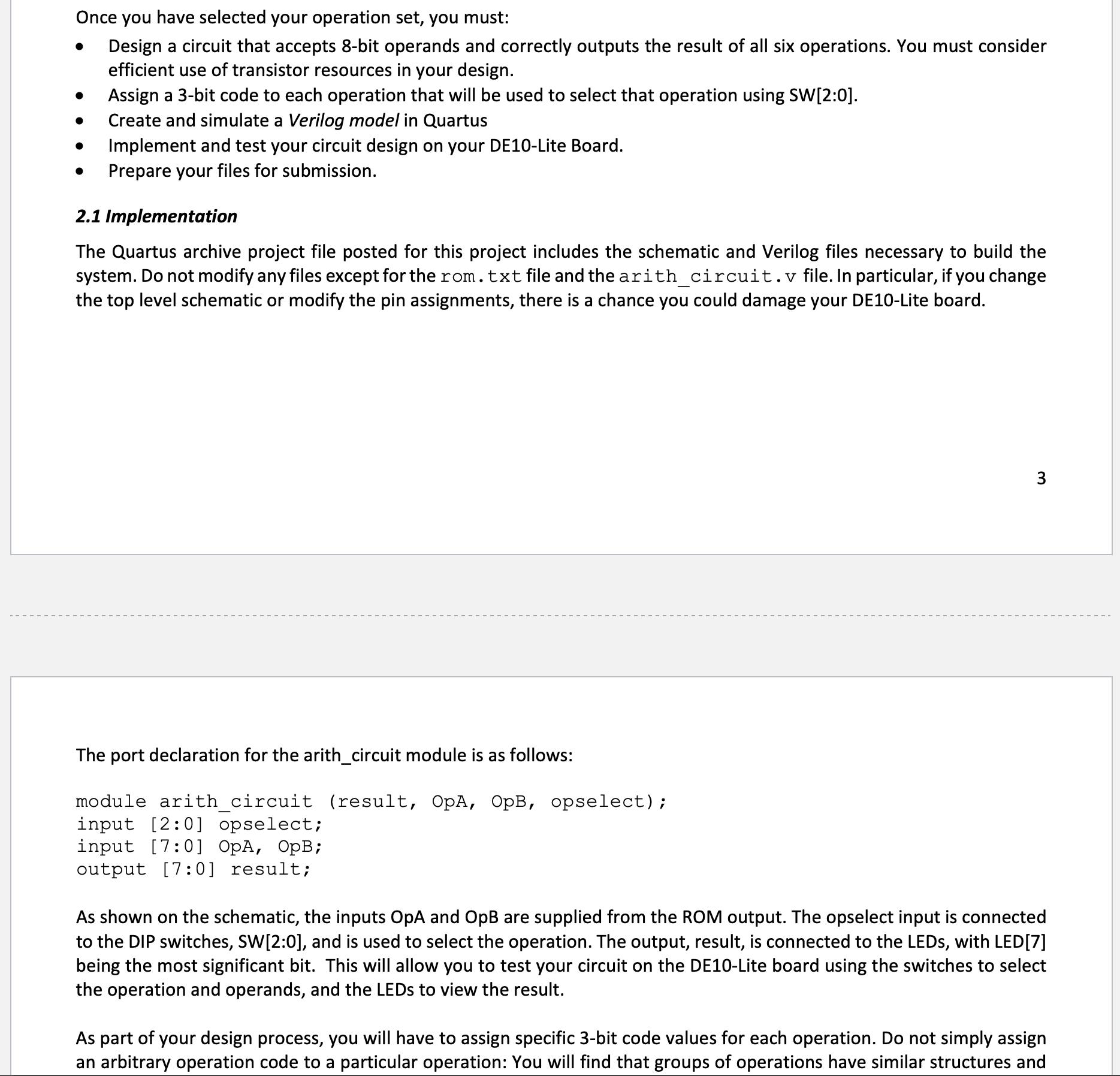
Once you have selected your operation set, you must: Design a circuit that accepts 8-bit operands and correctly outputs the result of all six operations. You must consider efficient use of transistor resources in your design. Assign a 3-bit code to each operation that will be used to select that operation using SW[2:0]. Create and simulate a Verilog model in Quartus Prepare your files for submission. Implement and test your circuit design on your DE10-Lite Board. 2.1 Implementation The Quartus archive project file posted for this project includes the schematic and Verilog files necessary to build the system. Do not modify any files except for the rom.txt file and the arith_circuit.v file. In particular, if you change the top level schematic or modify the pin assignments, there is a chance you could damage your DE10-Lite board. 3 The port declaration for the arith_circuit module is as follows: module arith_circuit (result, OpA, OpB, opselect); input [2:0] opselect; input [7:0] OpA, OpB; output [7:0] result; As shown on the schematic, the inputs OpA and OpB are supplied from the ROM output. The opselect input is connected to the DIP switches, SW[2:0], and is used to select the operation. The output, result, is connected to the LEDs, with LED[7] being the most significant bit. This will allow you to test your circuit on the DE10-Lite board using the switches to select the operation and operands, and the LEDs to view the result. As part of your design process, you will have to assign specific 3-bit code values for each operation. Do not simply assign an arbitrary operation code to a particular operation: You will find that groups of operations have similar structures and
Step by Step Solution
There are 3 Steps involved in it
Step: 1

Get Instant Access to Expert-Tailored Solutions
See step-by-step solutions with expert insights and AI powered tools for academic success
Step: 2

Step: 3

Ace Your Homework with AI
Get the answers you need in no time with our AI-driven, step-by-step assistance
Get Started


