Answered step by step
Verified Expert Solution
Question
1 Approved Answer
Need help with c++ program. Here is the UML for the expected final structure (see below for implementation tips) getoutputO: bool +prettyPrint(string padding) +linearPrinto Pin
Need help with c++ program.
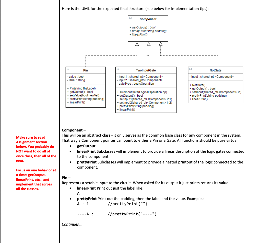
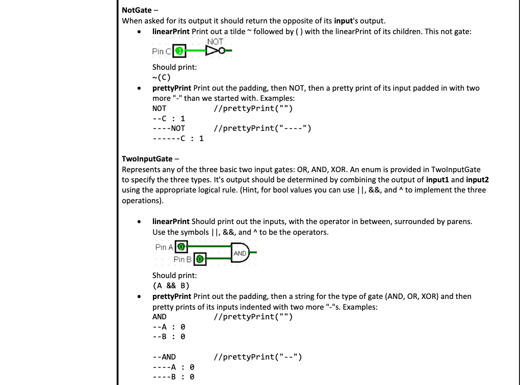
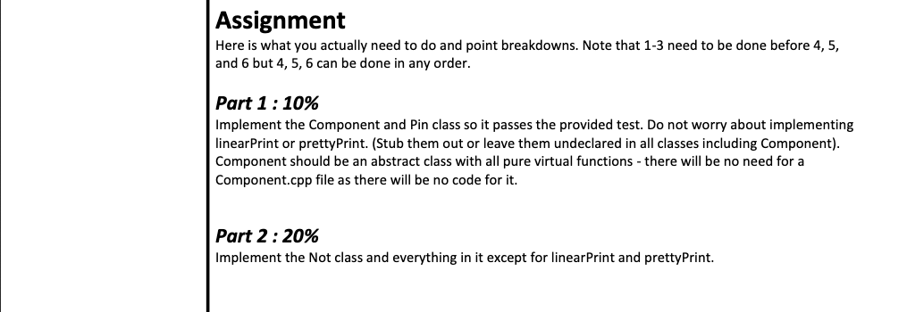
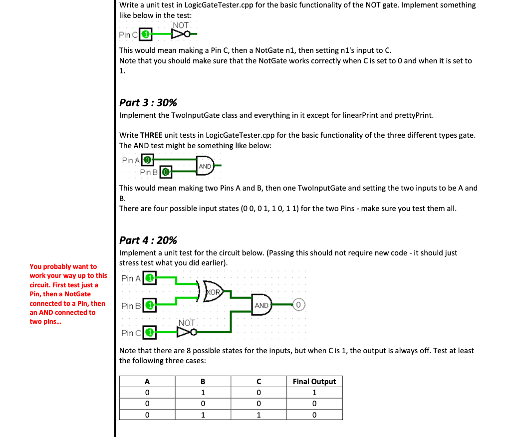
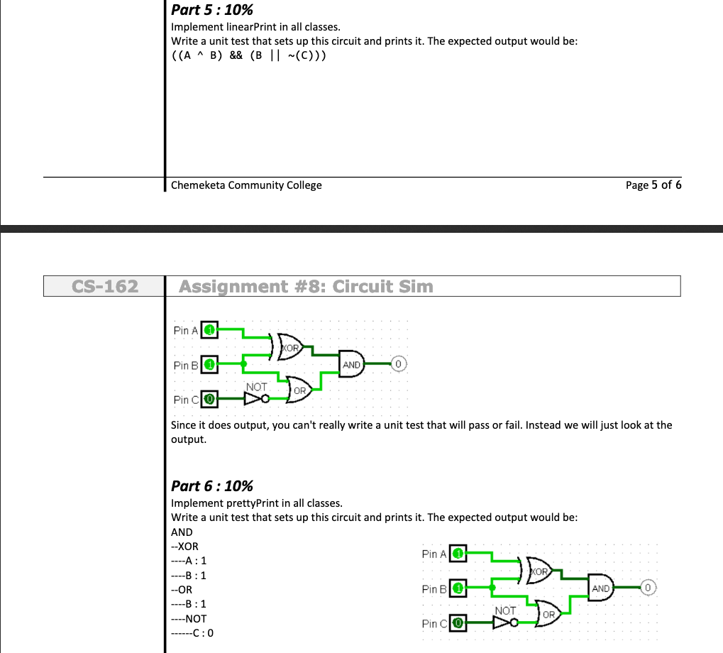

Here is the UML for the expected final structure (see below for implementation tips) getoutputO: bool +prettyPrint(string padding) +linearPrinto Pin TwolnputGate NotGate value bool - label: string input1: shared ptr Component- input: shared ptr Component- input2: shared_ptrcComponent gateType LogicOperation Pin(string theLabel) +getOutput: bool +setValue(bool newVal) +prettyPrint(string padding) linearPrinto TwolnputGate(LogicalOperation op) +getOutputo bool + setinput1(shared _ptr Component in1) +setinput(shared_ptr Component in2) + prettyPrint string padding) +linearPrinto +NotGate0 +getOutputo bool + setinput(shared_ptr Component> in) +prettyPrint string padding) + linearPrint Component- This will be an abstract class it only serves as the common base class for any component in the system That way a Component pointer can point to either a Pin or a Gate. All functions should be pure virtual Make sure to read Assignment section below. You probably do NOT want to do all of once class, then all of the next. getOutput linearPrint Subclasses will implement to provide a linear description of the logic gates connected to the component. prettyPrint Subclasses will implement to provide a nested printout of the logic connected to the component Focus on one behavior at a time: getOutput, linearPrint, etc... and implement that across all the classes Pin- Represents a setable input to the circuit. When asked for its output it just prints returns its value linearPrint Print out just the label like: prettyPrint Print out the padding, then the label and the value. Examples: //prettyPrint("") -A //prettyPrint("-") Continues... NotGate - When asked for its output it should return the opposite of its input's output linearPrint Print out a tilde followed by () with the linearPrint of its children. This not gate NOT Pin CO Should print ~(C) prettyPrint Print out the padding, then NOT, then a pretty print of its input padded in with two more"-" than we started with. Examples NOT //prettyPrint("") -NOT //prettyPrint("---") TwolnputGate - Represents any of the three basic two input gates: OR, AND, XOR. An enum is provided in TwolnputGate to specify the three types. It's output should be determined by combining the output of input1 and input2 using the appropriate logical rule. (Hint, for bool values you can use |1, &&, and A to implement the three operations) linearPrint Should print out the inputs, with the operator in between, surrounded by parens. Use the symbols ||, &&, and A to be the operators Pin A O AND Pin BO Should print (A && B) prettyPrint Print out the padding, then a string for the type of gate (AND, OR, XOR) and then pretty prints of its inputs indented with two more "-"s. Examples AND //prettyPrint("") AND //prettyPrint("--") Write a unit test in LogicGateTester.cpp for the basic functionality of the NOT gate. Implement something like below in the test: NOT This would mean making a Pin C, then a NotGate n1, then setting n1's input to C. Note that you should make sure that the NotGate works correctly when C is set to 0 and when it is set to Part 3 : 30% Implement the TwolnputGate class and everything in it except for linearPrint and prettyPrint Write THREE unit tests in LogicGateTester.cpp for the basic functionality of the three different types gate The AND test might be something like below: Pin A O Pin BO This would mean making two Pins A and B, then one TwolnputGate and setting the two inputs to be A and There are four possible input states (0 0, 01,1 0,11) for the two Pins make sure you test them all Part 4 : 20% Implement a unit test for the circuit below. (Passing this should not require new code - it should just stress test what you did earlier) You probably want to work your way up to thisPin A circuit. First test just a Pin, then a NotGate connected to a Pin, then Pin BO an AND connected to two pins... AND NOT Pin ClO Note that there are 8 possible states for the inputs, but when C is 1, the output is always off. Test at least the following three cases Final Output 0 0 0 0 0 0 0 Part 5 : 10% Implement linearPrint in all classes Write a unit test that sets up this circuit and prints it. The expected output would be Chemeketa Community College Page 5 of 6 CS-162 Assignment #8: Circuit Sim Pin A O Pin BO Pin CO Since it does output, you can't really write a unit test that will pass or fail. Instead we will just look at the OR AND 0 NOT OR output Part 6 : 10% Implement prettyPrint in all classes Write a unit test that sets up this circuit and prints it. The expected output would be AND -XOR Pin AlO Pin BO Pin ClO OR -OR AND 0 NOT OR ..--NOT C:0 Note that the first component is printed with no padding. Each additional layer is printed with a two more -- of padding than the previous layer so that they are nested like an outline. Here is the UML for the expected final structure (see below for implementation tips) getoutputO: bool +prettyPrint(string padding) +linearPrinto Pin TwolnputGate NotGate value bool - label: string input1: shared ptr Component- input: shared ptr Component- input2: shared_ptrcComponent gateType LogicOperation Pin(string theLabel) +getOutput: bool +setValue(bool newVal) +prettyPrint(string padding) linearPrinto TwolnputGate(LogicalOperation op) +getOutputo bool + setinput1(shared _ptr Component in1) +setinput(shared_ptr Component in2) + prettyPrint string padding) +linearPrinto +NotGate0 +getOutputo bool + setinput(shared_ptr Component> in) +prettyPrint string padding) + linearPrint Component- This will be an abstract class it only serves as the common base class for any component in the system That way a Component pointer can point to either a Pin or a Gate. All functions should be pure virtual Make sure to read Assignment section below. You probably do NOT want to do all of once class, then all of the next. getOutput linearPrint Subclasses will implement to provide a linear description of the logic gates connected to the component. prettyPrint Subclasses will implement to provide a nested printout of the logic connected to the component Focus on one behavior at a time: getOutput, linearPrint, etc... and implement that across all the classes Pin- Represents a setable input to the circuit. When asked for its output it just prints returns its value linearPrint Print out just the label like: prettyPrint Print out the padding, then the label and the value. Examples: //prettyPrint("") -A //prettyPrint("-") Continues... NotGate - When asked for its output it should return the opposite of its input's output linearPrint Print out a tilde followed by () with the linearPrint of its children. This not gate NOT Pin CO Should print ~(C) prettyPrint Print out the padding, then NOT, then a pretty print of its input padded in with two more"-" than we started with. Examples NOT //prettyPrint("") -NOT //prettyPrint("---") TwolnputGate - Represents any of the three basic two input gates: OR, AND, XOR. An enum is provided in TwolnputGate to specify the three types. It's output should be determined by combining the output of input1 and input2 using the appropriate logical rule. (Hint, for bool values you can use |1, &&, and A to implement the three operations) linearPrint Should print out the inputs, with the operator in between, surrounded by parens. Use the symbols ||, &&, and A to be the operators Pin A O AND Pin BO Should print (A && B) prettyPrint Print out the padding, then a string for the type of gate (AND, OR, XOR) and then pretty prints of its inputs indented with two more "-"s. Examples AND //prettyPrint("") AND //prettyPrint("--") Write a unit test in LogicGateTester.cpp for the basic functionality of the NOT gate. Implement something like below in the test: NOT This would mean making a Pin C, then a NotGate n1, then setting n1's input to C. Note that you should make sure that the NotGate works correctly when C is set to 0 and when it is set to Part 3 : 30% Implement the TwolnputGate class and everything in it except for linearPrint and prettyPrint Write THREE unit tests in LogicGateTester.cpp for the basic functionality of the three different types gate The AND test might be something like below: Pin A O Pin BO This would mean making two Pins A and B, then one TwolnputGate and setting the two inputs to be A and There are four possible input states (0 0, 01,1 0,11) for the two Pins make sure you test them all Part 4 : 20% Implement a unit test for the circuit below. (Passing this should not require new code - it should just stress test what you did earlier) You probably want to work your way up to thisPin A circuit. First test just a Pin, then a NotGate connected to a Pin, then Pin BO an AND connected to two pins... AND NOT Pin ClO Note that there are 8 possible states for the inputs, but when C is 1, the output is always off. Test at least the following three cases Final Output 0 0 0 0 0 0 0 Part 5 : 10% Implement linearPrint in all classes Write a unit test that sets up this circuit and prints it. The expected output would be Chemeketa Community College Page 5 of 6 CS-162 Assignment #8: Circuit Sim Pin A O Pin BO Pin CO Since it does output, you can't really write a unit test that will pass or fail. Instead we will just look at the OR AND 0 NOT OR output Part 6 : 10% Implement prettyPrint in all classes Write a unit test that sets up this circuit and prints it. The expected output would be AND -XOR Pin AlO Pin BO Pin ClO OR -OR AND 0 NOT OR ..--NOT C:0 Note that the first component is printed with no padding. Each additional layer is printed with a two more -- of padding than the previous layer so that they are nested like an outline
Step by Step Solution
There are 3 Steps involved in it
Step: 1

Get Instant Access to Expert-Tailored Solutions
See step-by-step solutions with expert insights and AI powered tools for academic success
Step: 2

Step: 3

Ace Your Homework with AI
Get the answers you need in no time with our AI-driven, step-by-step assistance
Get Started


