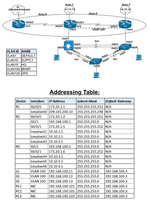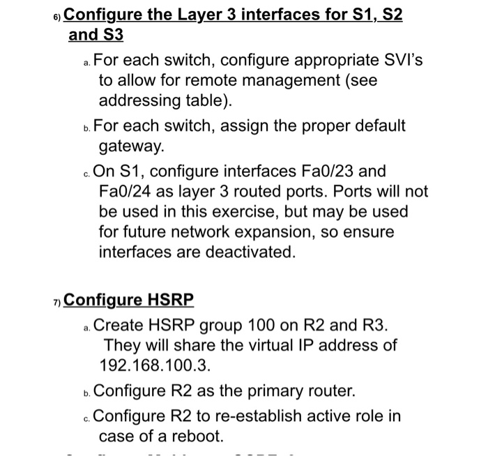
need help with question 6 and 7 and commands needed ti excute on cisco switch and router. packet tracer anything can help use topology and table for guidence.
Smulated internet) sovar z 50/0/2 so// OCE ---HSRP Foodi --MSRP 100- Foods Foods Fall/3 Fooja Foods 53 Falls Feb/2 pol Fo/2 hath P2 VLAN ID NAME VLAN1 DEFAULT VLAN 10 SUPPLY VLAN 15 HQ VLAN100 MGMT VLAN120 OPS Addressing Table: Device Interface IP Address Subnet Mask Default Gateway so/0/0 172.20.1.1 255.255.255.252 N/A Loopbacko 209.165.200.10 255.255.255.248 N/A S0/0/0 172.20.1.2 255.255.255.252 N/A G0/1 192.168.100.1 255.255.255.0 N/A S0/0/1 172.20.1.5 255.255.255.252 N/A Loopback1 10.10.1.1 255.255.255.0 N/A Loopback2 10.10.2.1 255.255.255.0 N/A Loopback3 10.10.3.1 255.255.255.0 N/A G0/ 1 192.168.100.2 255.255.255.0 N/A so/0/1 172.20.1.6 255.255.255.252 N/A Loopback4 10.10.4.1 255.255.255.0 N/A Loopbacks 10.10.5.1 255.255.255.0 N/A Loopback6 10.10.6.1 255.255.255.0 IN/A VLAN 100 192.168.100.11 255.255.255.0 192.168.100.3 VLAN 100 192.168.100.12 255.255.255.0 192.168.100.3 VLAN 100 192.168.100.13 255.255.255.0 192.168.100.3 NIC 192.168.100.101 255.255.255.0 192.168.100.3 NIC 192.168.100.102 255.255.255.0 192.168.100.3 NIC 192.168.100.103 255.255.255.0 192.168.100.3 PC 6) Configure the Layer 3 interfaces for S1, S2 and S3 a. For each switch, configure appropriate SVI's to allow for remote management (see addressing table). b. For each switch, assign the proper default gateway. c. On S1, configure interfaces Fa0/23 and Fa0/24 as layer 3 routed ports. Ports will not be used in this exercise, but may be used for future network expansion, so ensure interfaces are deactivated. 7) Configure HSRP a. Create HSRP group 100 on R2 and R3. They will share the virtual IP address of 192.168.100.3. b. Configure R2 as the primary router. Configure R2 to re-establish active role in case of a reboot. Smulated internet) sovar z 50/0/2 so// OCE ---HSRP Foodi --MSRP 100- Foods Foods Fall/3 Fooja Foods 53 Falls Feb/2 pol Fo/2 hath P2 VLAN ID NAME VLAN1 DEFAULT VLAN 10 SUPPLY VLAN 15 HQ VLAN100 MGMT VLAN120 OPS Addressing Table: Device Interface IP Address Subnet Mask Default Gateway so/0/0 172.20.1.1 255.255.255.252 N/A Loopbacko 209.165.200.10 255.255.255.248 N/A S0/0/0 172.20.1.2 255.255.255.252 N/A G0/1 192.168.100.1 255.255.255.0 N/A S0/0/1 172.20.1.5 255.255.255.252 N/A Loopback1 10.10.1.1 255.255.255.0 N/A Loopback2 10.10.2.1 255.255.255.0 N/A Loopback3 10.10.3.1 255.255.255.0 N/A G0/ 1 192.168.100.2 255.255.255.0 N/A so/0/1 172.20.1.6 255.255.255.252 N/A Loopback4 10.10.4.1 255.255.255.0 N/A Loopbacks 10.10.5.1 255.255.255.0 N/A Loopback6 10.10.6.1 255.255.255.0 IN/A VLAN 100 192.168.100.11 255.255.255.0 192.168.100.3 VLAN 100 192.168.100.12 255.255.255.0 192.168.100.3 VLAN 100 192.168.100.13 255.255.255.0 192.168.100.3 NIC 192.168.100.101 255.255.255.0 192.168.100.3 NIC 192.168.100.102 255.255.255.0 192.168.100.3 NIC 192.168.100.103 255.255.255.0 192.168.100.3 PC 6) Configure the Layer 3 interfaces for S1, S2 and S3 a. For each switch, configure appropriate SVI's to allow for remote management (see addressing table). b. For each switch, assign the proper default gateway. c. On S1, configure interfaces Fa0/23 and Fa0/24 as layer 3 routed ports. Ports will not be used in this exercise, but may be used for future network expansion, so ensure interfaces are deactivated. 7) Configure HSRP a. Create HSRP group 100 on R2 and R3. They will share the virtual IP address of 192.168.100.3. b. Configure R2 as the primary router. Configure R2 to re-establish active role in case of a reboot
 need help with question 6 and 7 and commands needed ti excute on cisco switch and router. packet tracer anything can help use topology and table for guidence.


