Answered step by step
Verified Expert Solution
Question
1 Approved Answer
Need help with solving that exercice, completely stuck. Consider a offshore upstream oil & gas pipeline process. Here, undesired cyclic pressure and flow oscillations (referred


Need help with solving that exercice, completely stuck.
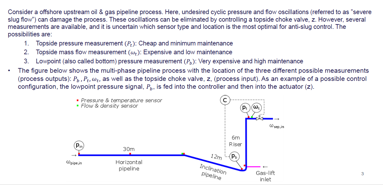
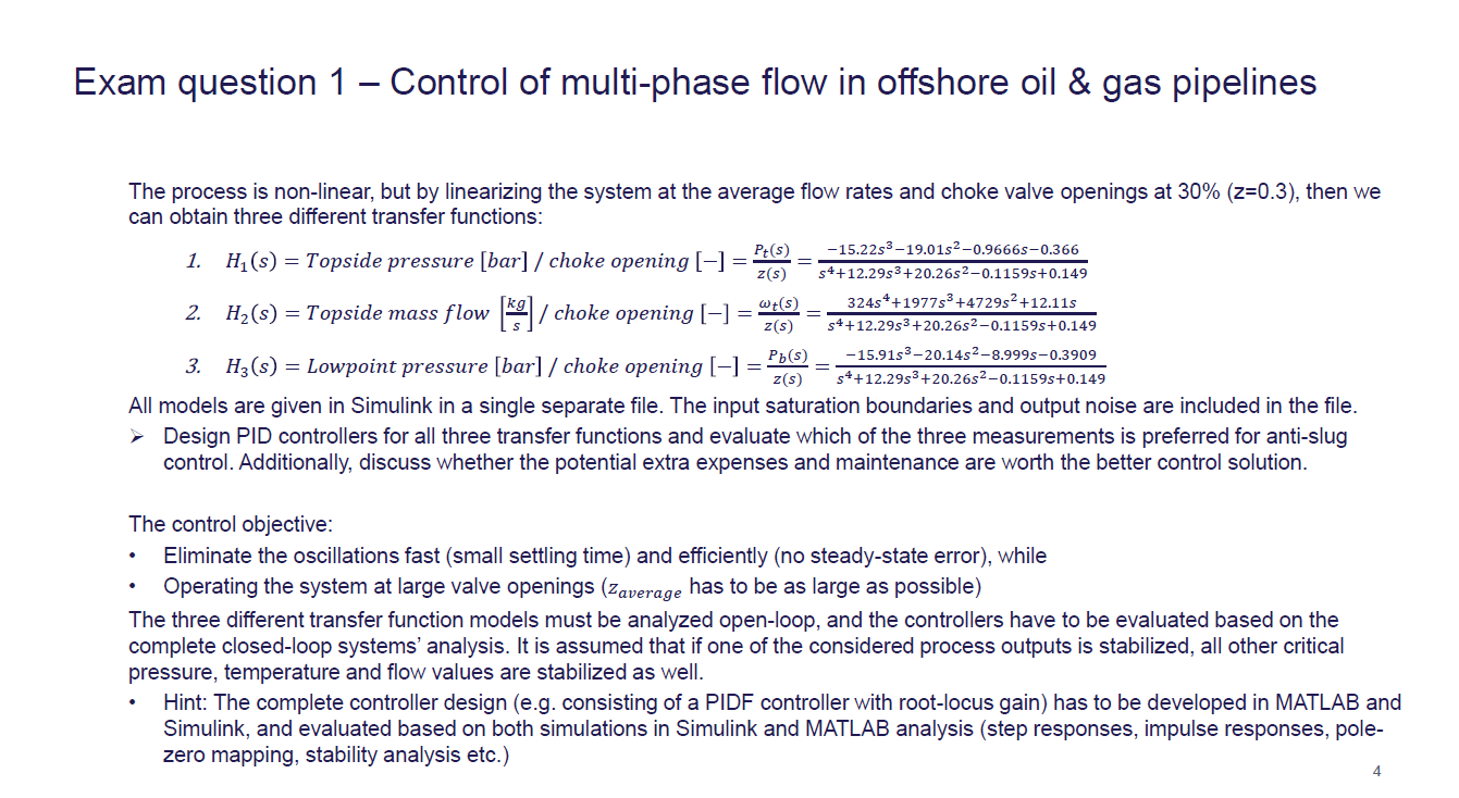
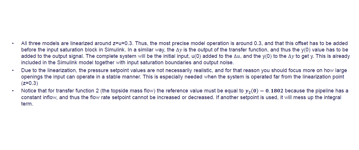
Consider a offshore upstream oil \& gas pipeline process. Here, undesired cyclic pressure and flow oscillations (referred to as "severe slug flow") can damage the process. These oscillations can be eliminated by controlling a topside choke valve, z. However, several measurements are available, and it is uncertain which sensor type and location is the most optimal for anti-slug control. The possibilities are: 1. Topside pressure measurement (Pt) : Cheap and minimum maintenance 2. Topside mass flow measurement (t) : Expensive and low maintenance 3. Lowpoint (also called bottom) pressure measurement (Pb) : Very expensive and high maintenance - The figure below shows the multi-phase pipeline process with the location of the three different possible measurements (process outputs): Pb,Pt,t, as well as the topside choke valve, z, (process input). As an example of a possible control configuration, the lowpoint pressure signal, Pb, is fed into the controller and then into the actuator (z). Exam question 1 - Control of multi-phase flow in offshore oil \& gas pipelines The process is non-linear, but by linearizing the system at the average flow rates and choke valve openings at 30%(z=0.3), then we can obtain three different transfer functions: 1. H1(s)= Topside pressure [ bar ]/ choke opening []=z(s)Pt(s)=s4+12.29s3+20.26s20.1159s+0.14915.22s319.01s20.9666s0.366 2. H2(s)= Topside mass flow [skg]/ choke opening []=z(s)t(s)=s4+12.29s3+20.26s20.1159s+0.149324s4+1977s3+4729s2+12.11s 3. H3(s)= Lowpoint pressure [ bar ]/ choke opening []=z(s)Pb(s)=s4+12.29s3+20.26s20.1159s+0.14915.91s320.14s28.999s0.3909 All models are given in Simulink in a single separate file. The input saturation boundaries and output noise are included in the file. > Design PID controllers for all three transfer functions and evaluate which of the three measurements is preferred for anti-slug control. Additionally, discuss whether the potential extra expenses and maintenance are worth the better control solution. The control objective: - Eliminate the oscillations fast (small settling time) and efficiently (no steady-state error), while - Operating the system at large valve openings (zaverage has to be as large as possible) The three different transfer function models must be analyzed open-loop, and the controllers have to be evaluated based on the complete closed-loop systems' analysis. It is assumed that if one of the considered process outputs is stabilized, all other critical pressure, temperature and flow values are stabilized as well. - Hint: The complete controller design (e.g. consisting of a PIDF controller with root-locus gain) has to be developed in MATLAB and Simulink, and evaluated based on both simulations in Simulink and MATLAB analysis (step responses, impulse responses, polezero mapping, stability analysis etc.) 4 All three models are linearized around z=u=0.3. Thus, the most precise model operation is around 0.3 , and that this offset has to be added before the input saturation block in Simulink. In a similar way, the y is the output of the transfer function, and thus the y(0) value has to be added to the output signal. The complete system will be the initial input, u(0) added to the u, and the y(0) to the y to get y. This is already included in the Simulink model together with input saturation boundaries and output noise. Due to the linearization, the pressure setpoint values are not necessarily realistic, and for that reason you should focus more on how large openings the input can operate in a stable manner. This is especially needed when the system is operated far from the linearization point (z=0.3) - Notice that for transfer function 2 (the topside mass flow) the reference value must be equal to y2(0)=0.1802 because the pipeline has a constant inflow, and thus the flow rate setpoint cannot be increased or decreased. If another setpoint is used, it will mess up the integral termStep by Step Solution
There are 3 Steps involved in it
Step: 1

Get Instant Access to Expert-Tailored Solutions
See step-by-step solutions with expert insights and AI powered tools for academic success
Step: 2

Step: 3

Ace Your Homework with AI
Get the answers you need in no time with our AI-driven, step-by-step assistance
Get Started


