Need help with this lab assignment. It needs to be programmed in c. I have been trying to figure it out for hours but I can't figure it out. If someone could provide pseudocode or some sort of breakdown as to how this could be done it would be greatly appreciated.


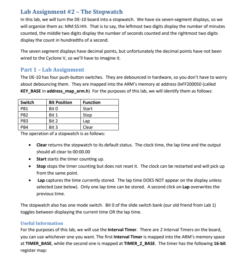
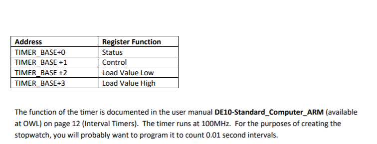
Lab Assignment #2 - The Stopwatch In this lab, we will turn the DE-10 board into a stopwatch. We have six seven-segment displays, so we will organize them as: MM:SS:HH. That is to say, the leftmost two digits display the number of minutes counted, the middle two digits display the number of seconds counted and the rightmost two digits display the count in hundredths of a second. The seven segment displays have decimal points, but unfortunately the decimal points have not been wired to the Cyclone V, so we'll have to imagine it. Part 1 - Lab Assignment The DE-10 has four push-button switches. They are debounced in hardware, so you don't have to worry about debouncing them. They are mapped into the ARM's memory at address OxFF200050 (called KEY_BASE in address_map_arm.h) For the purposes of this lab, we will identify them as follows: Switch Bit Position Function PB1 Bit 0 Start PB2 Bit 1 Stop PB3 Bit 2 Lap PB4 Bit 3 Clear The operation of a stopwatch is as follows: Clear returns the stopwatch to its default status. The clock time, the lap time and the output should all clear to 00:00.00 Start starts the timer counting up. Stop stops the timer counting but does not reset it. The clock can be restarted and will pick up from the same point. Lap captures the time currently stored. The lap time DOES NOT appear on the display unless selected (see below). Only one lap time can be stored. A second click on Lap overwrites the previous time. The stopwatch also has one mode switch. Bit 0 of the slide switch bank (our old friend from Lab 1) toggles between displaying the current time OR the lap time. Useful Information For the purposes of this lab, we will use the Interval Timer. There are 2 Interval Timers on the board, you can use whichever one you want. The first Interval Timer is mapped into the ARM's memory space at TIMER BASE, while the second one is mapped at TIMER_2_BASE. The timer has the following 16-bit register map: Address TIMER_BASE+0 TIMER BASE +1 TIMER BASE +2 TIMER_BASE+3 Register Function Status Control Load Value Low Load Value High The function of the timer is documented in the user manual DE10-Standard_Computer_ARM (available at OWL) on page 12 (Interval Timers). The timer runs at 100MHz. For the purposes of creating the stopwatch, you will probably want to program it to count 0.01 second intervals. Lab Assignment #2 - The Stopwatch In this lab, we will turn the DE-10 board into a stopwatch. We have six seven-segment displays, so we will organize them as: MM:SS:HH. That is to say, the leftmost two digits display the number of minutes counted, the middle two digits display the number of seconds counted and the rightmost two digits display the count in hundredths of a second. The seven segment displays have decimal points, but unfortunately the decimal points have not been wired to the Cyclone V, so we'll have to imagine it. Part 1 - Lab Assignment The DE-10 has four push-button switches. They are debounced in hardware, so you don't have to worry about debouncing them. They are mapped into the ARM's memory at address OxFF200050 (called KEY_BASE in address_map_arm.h) For the purposes of this lab, we will identify them as follows: Switch Bit Position Function PB1 Bit 0 Start PB2 Bit 1 Stop PB3 Bit 2 Lap PB4 Bit 3 Clear The operation of a stopwatch is as follows: Clear returns the stopwatch to its default status. The clock time, the lap time and the output should all clear to 00:00.00 Start starts the timer counting up. Stop stops the timer counting but does not reset it. The clock can be restarted and will pick up from the same point. Lap captures the time currently stored. The lap time DOES NOT appear on the display unless selected (see below). Only one lap time can be stored. A second click on Lap overwrites the previous time. The stopwatch also has one mode switch. Bit 0 of the slide switch bank (our old friend from Lab 1) toggles between displaying the current time OR the lap time. Useful Information For the purposes of this lab, we will use the Interval Timer. There are 2 Interval Timers on the board, you can use whichever one you want. The first Interval Timer is mapped into the ARM's memory space at TIMER BASE, while the second one is mapped at TIMER_2_BASE. The timer has the following 16-bit register map: Address TIMER_BASE+0 TIMER BASE +1 TIMER BASE +2 TIMER_BASE+3 Register Function Status Control Load Value Low Load Value High The function of the timer is documented in the user manual DE10-Standard_Computer_ARM (available at OWL) on page 12 (Interval Timers). The timer runs at 100MHz. For the purposes of creating the stopwatch, you will probably want to program it to count 0.01 second intervals


