Question
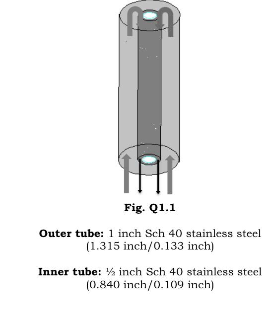
Q2. Considering the system given in Fig. Q1.1, a) In which position and where should you place the control volume in order to find


Q2. Considering the system given in Fig. Q1.1, a) In which position and where should you place the control volume in order to find the velocity distribution within the liquid film? Show on the film flow. [3 pts] b) Schematically plot velocity and shear stress distributions for the liquid film flow on the Fig. Q1.1. [4 pts] c) Show the interfaces and write boundary conditions, explaining the reasons basing on molecular interactions for the film flow. [8 pts] NOR HIP Fig. Q1.1 Outer tube: 1 inch Sch 40 stainless steel (1.315 inch/0.133 inch) Inner tube: inch Sch 40 stainless steel (0.840 inch/0.109 inch)
Step by Step Solution
There are 3 Steps involved in it
Step: 1
a How and where should the control volume be positioned to determine the distribution of velocities ...
Get Instant Access to Expert-Tailored Solutions
See step-by-step solutions with expert insights and AI powered tools for academic success
Step: 2

Step: 3

Ace Your Homework with AI
Get the answers you need in no time with our AI-driven, step-by-step assistance
Get StartedRecommended Textbook for
Fundamentals of Heat and Mass Transfer
Authors: Incropera, Dewitt, Bergman, Lavine
6th Edition
978-0470055540, 471457280, 470881453, 470055545, 978-0470881453, 978-0471457282
Students also viewed these Chemical Engineering questions
Question
Answered: 1 week ago
Question
Answered: 1 week ago
Question
Answered: 1 week ago
Question
Answered: 1 week ago
Question
Answered: 1 week ago
Question
Answered: 1 week ago
Question
Answered: 1 week ago
Question
Answered: 1 week ago
Question
Answered: 1 week ago
Question
Answered: 1 week ago
Question
Answered: 1 week ago
Question
Answered: 1 week ago
Question
Answered: 1 week ago
Question
Answered: 1 week ago
Question
Answered: 1 week ago
Question
Answered: 1 week ago
Question
Answered: 1 week ago
View Answer in SolutionInn App


