Answered step by step
Verified Expert Solution
Question
1 Approved Answer
Notes: Units are to be SI. Convert CFM (cubic feet per minute) to L/s and feet to mm. Question 1 The floor plan below
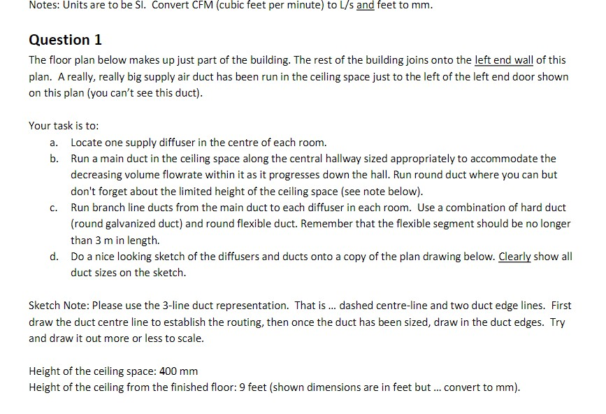
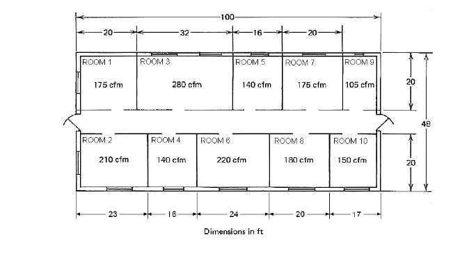
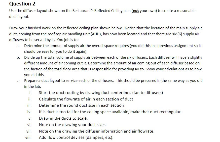
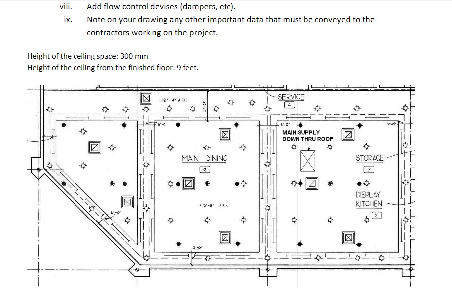

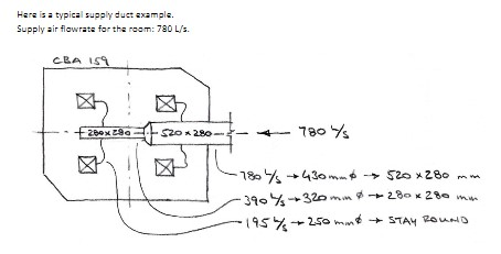
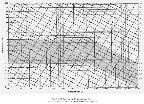
Notes: Units are to be SI. Convert CFM (cubic feet per minute) to L/s and feet to mm. Question 1 The floor plan below makes up just part of the building. The rest of the building joins onto the left end wall of this plan. A really, really big supply air duct has been run in the ceiling space just to the left of the left end door shown on this plan (you can't see this duct). Your task is to: a. Locate one supply diffuser in the centre of each room. b. Run a main duct in the ceiling space along the central hallway sized appropriately to accommodate the decreasing volume flowrate within it as it progresses down the hall. Run round duct where you can but don't forget about the limited height of the ceiling space (see note below). Run branch line ducts from the main duct to each diffuser in each room. Use a combination of hard duct (round galvanized duct) and round flexible duct. Remember that the flexible segment should be no longer than 3 m in length. d. Do a nice looking sketch of the diffusers and ducts onto a copy of the plan drawing below. Clearly show all duct sizes on the sketch. C. Sketch Note: Please use the 3-line duct representation. That is ... dashed centre-line and two duct edge lines. First draw the duct centre line to establish the routing, then once the duct has been sized, draw in the duct edges. Try and draw it out more or less to scale. Height of the ceiling space: 400 mm Height of the ceiling from the finished floor: 9 feet (shown dimensions are in feet but ... convert to mm). 20- ROOM 1 175 cfm ROOM 2 210 cfm 23 ROOM 3 32 280 cfm ROOM 4 140 cfm 16 -100- ROOM 6 ROOM 5 16- 220 cfm 24 140 cfm Dimensions in ft ROOM 7 20 175 cfm ROOM 8 180 cfm 20 ROOM 9 105 cfm ROOM 10 150 cfm 20 20 48 Question 2 Use the diffuser layout shown on the Restaurant's Reflected Ceiling plan (not your own) to create a reasonable duct layout. Draw your finished work on the reflected ceiling plan shown below. Notice that the location of the main supply air duct, coming from the roof top air handling unit (AHU), has now been located and that there are six (6) supply air diffusers to be served by it. You job is to: a. Determine the amount of supply air the overall space requires (you did this in a previous assignment so it should be easy for you to do it again). b. Divide up the total volume of supply air between each of the six diffusers. Each diffuser will have a slightly different amount of air coming out it. Determine the amount of air coming out of each diffuser based on the faction of the total floor area that is responsible for providing air to. Show your calculations as to how you did this. c. Prepare a duct layout to service each of the diffusers. This should be prepared in the same way as you did in the lab: i. ii. iii. iv. V. vi. vii. viii. Start the duct routing by drawing duct centerlines (fan to diffusers) Calculate the flowrate of air in each section of duct Determine the round duct size in each section If is duct is too tall for the ceiling space available, make that duct rectangular. Draw in the ducts to scale. Note on the drawing your duct sizes Note on the drawing the diffuser information and air flowrate. Add flow control devises (dampers, etc). viii. ix. Add flow control devises (dampers, etc). Note on your drawing any other important data that must be conveyed to the contractors working on the project. Height of the ceiling space: 300 mm Height of the ceiling from the finished floor: 9 feet. a X +12-4 A.R.R. MAIN DINING g 2'-0" 13-8 AFF Q -SERVICE 4 8-0 MAIN SUPPLY DOWN THRU ROOF STORACE DISPLAY KITCHEN 8 To use this chart you must follow these simple rules: Low Velocity Design: Supply Air Ducts use: 0.8 Pa/m (0.1" H:0/100 feet) Return Air Duct use: 0.65 Pa/m (0.08" H0/100 feet) 0 High Valority Desin Here is a typical supply duct example. Supply air flowrate for the room: 780 L/s. CBA 159 8 260x290 $20 x 280 780 % -780 / +430mm & 520 x 280 mm 390/320 mm 280 x 280 mm 195%250 min STAY ROUND FRICTION LOBS, Pam 100 70 60 2 40 90 20 10 7 5 1 0.7 05 0,4 03 0.2 023 60 100 200 500 1000 2000 AIR QUANTITY, L/ 5000 10000 Fig. 9-2 SI Friction of Air In Straight Ducts Figure 9, Chapter 21, 2013 ASHRAX Handok-Funda 20 000 VELOCITY Play S 60 000 100 000 son DACT CRAMETER, 100 70 50 40 30 20 10 16.0 5 3 2 07 0.5 0.4 0.3 0.2 200 000
Step by Step Solution
There are 3 Steps involved in it
Step: 1
Dynamic process modeling is a type of process modeling that captures timedependent behaviors meaning it takes into account how the process changes ove...
Get Instant Access to Expert-Tailored Solutions
See step-by-step solutions with expert insights and AI powered tools for academic success
Step: 2

Step: 3

Ace Your Homework with AI
Get the answers you need in no time with our AI-driven, step-by-step assistance
Get Started


