

Answered step by step
Verified Expert Solution
Question
1 Approved Answer
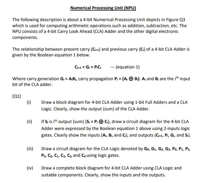
Numerical Processing Unit (NPU) The following description is about a 4-bit Numerical Processing Unit depicts in Figure Q3 which is used for computing arithmetic operations
Step by Step Solution
There are 3 Steps involved in it
Step: 1

Get Instant Access to Expert-Tailored Solutions
See step-by-step solutions with expert insights and AI powered tools for academic success
Step: 2

Step: 3
Ace Your Homework with AI
Get the answers you need in no time with our AI-driven, step-by-step assistance
Get Started
Sams Teach Yourself Beginning Databases In 24 Hours
Authors: Ryan Stephens, Ron Plew
1st Edition
067232492X, 978-0672324925