Answered step by step
Verified Expert Solution
Question
1 Approved Answer
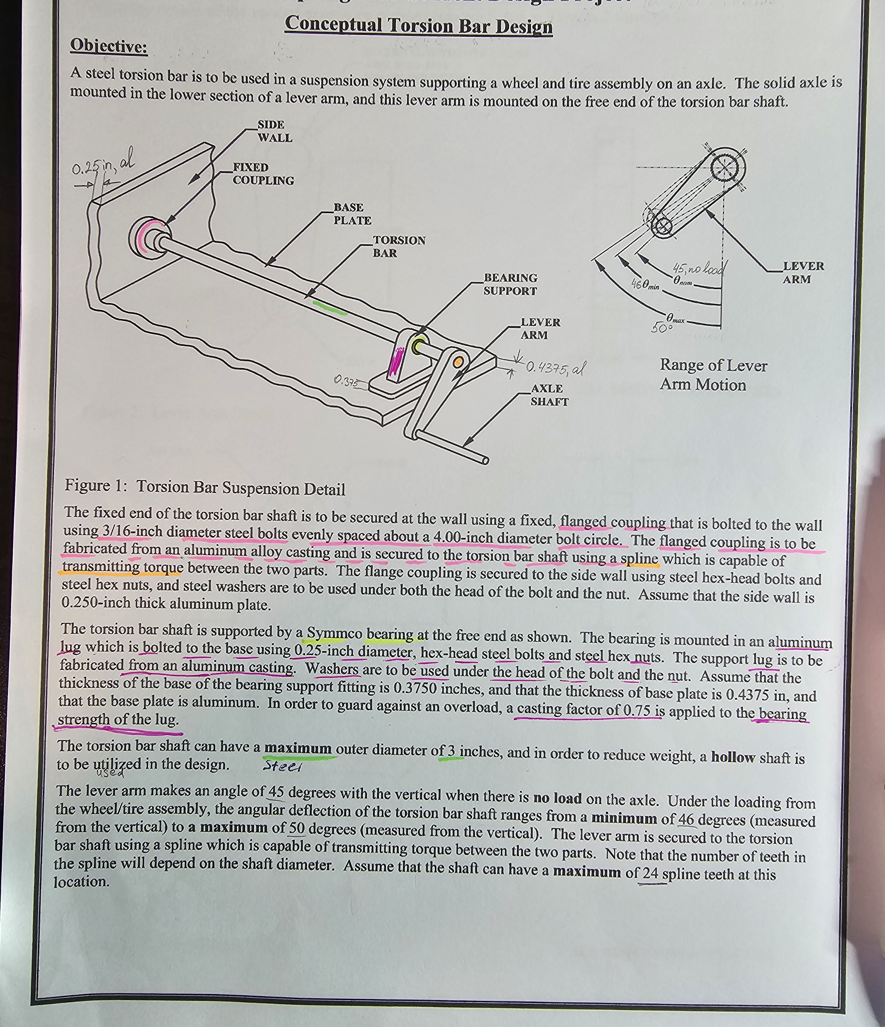
Objective: Conceptual Torsion Bar Design A steel torsion bar is to be used in a suspension system supporting a wheel and tire assembly on


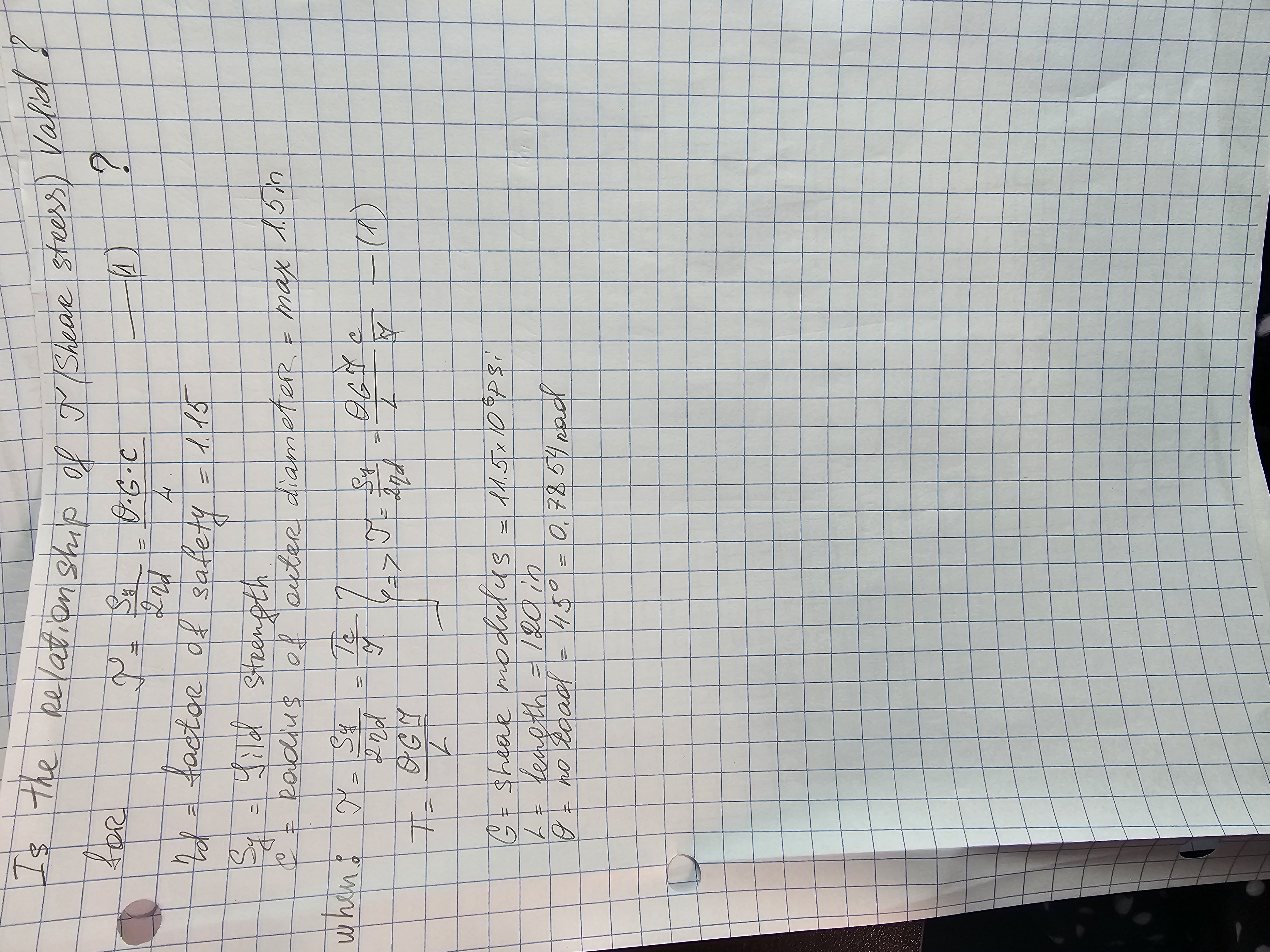
Objective: Conceptual Torsion Bar Design A steel torsion bar is to be used in a suspension system supporting a wheel and tire assembly on an axle. The solid axle is mounted in the lower section of a lever arm, and this lever arm is mounted on the free end of the torsion bar shaft. 1.25in, al SIDE WALL FIXED COUPLING BASE PLATE 0.375 TORSION BAR BEARING SUPPORT LEVER ARM 0.4375, al AXLE SHAFT 45, no load LEVER ARM 460min Onom Oma 50 Range of Lever Arm Motion Figure 1: Torsion Bar Suspension Detail The fixed end of the torsion bar shaft is to be secured at the wall using a fixed, flanged coupling that is bolted to the wall using 3/16-inch diameter steel bolts evenly spaced about a 4.00-inch diameter bolt circle. The flanged coupling is to be fabricated from an aluminum alloy casting and is secured to the torsion bar shaft using a spline which is capable of transmitting torque between the two parts. The flange coupling is secured to the side wall using steel hex-head bolts and steel hex nuts, and steel washers are to be used under both the head of the bolt and the nut. Assume that the side wall is 0.250-inch thick aluminum plate. The torsion bar shaft is supported by a Symmco bearing at the free end as shown. The bearing is mounted in an aluminum lug which is bolted to the base using 0.25-inch diameter, hex-head steel bolts and steel hex nuts. The support lug is to be fabricated from an aluminum casting. Washers are to be used under the head of the bolt and the nut. Assume that the thickness of the base of the bearing support fitting is 0.3750 inches, and that the thickness of base plate is 0.4375 in, and that the base plate is aluminum. In order to guard against an overload, a casting factor of 0.75 is applied to the bearing strength of the lug. The torsion bar shaft can have a maximum outer diameter of 3 inches, and in order to reduce weight, a hollow shaft is to be utilized in the design. Steel used The lever arm makes an angle of 45 degrees with the vertical when there is no load on the axle. Under the loading from the wheel/tire assembly, the angular deflection of the torsion bar shaft ranges from a minimum of 46 degrees (measured from the vertical) to a maximum of 50 degrees (measured from the vertical). The lever arm is secured to the torsion bar shaft using a spline which is capable of transmitting torque between the two parts. Note that the number of teeth in the spline will depend on the shaft diameter. Assume that the shaft can have a maximum of 24 spline teeth at this location. Is the FOR nd = Relationship of T Shear stress) Valid I 2nd 0.6.C 4 = factor of safety = 1.15 Sild Strength 1 ? Radius of outer diameter = max 1.5in Sy 46,013-0676-10 when M=Sy Te 2nd QGI 2nd G = shear modulus L = length = 120 in = 11.5x10Psi 0 = no road = 45 = 0.7854 Rad
Step by Step Solution
There are 3 Steps involved in it
Step: 1

Get Instant Access to Expert-Tailored Solutions
See step-by-step solutions with expert insights and AI powered tools for academic success
Step: 2

Step: 3

Ace Your Homework with AI
Get the answers you need in no time with our AI-driven, step-by-step assistance
Get Started


