Question
Objectives Part 1. Perform basic router configuration (6pts) Part 2. Configure OSPF (36pts) Part 3. Configure DHCP (24pts) Part 4. Configure switch security (53pts) Part

Objectives Part 1. Perform basic router configuration (6pts) Part 2. Configure OSPF (36pts) Part 3. Configure DHCP (24pts) Part 4. Configure switch security (53pts) Part 5. Configure ACLs (30pts)
Instructions
All given device names are case sensitive!
Part 1. Perform basic router configuration (6pts)
Step 1. On R10 configure a hostname R10 (1pt)
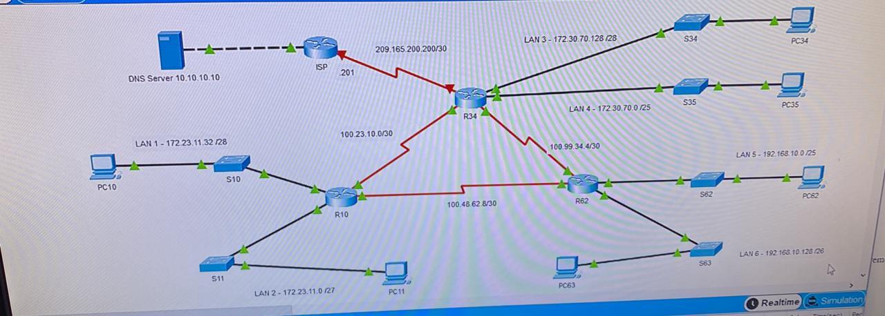
Step 2. On R34 (4pts) a) Configure a hostname R34 (1pt) b) Configure IP addresing on the serial 0/1/1 interface. Assign the second usable address of the 209.165.200.200/30 network (3pts)
Step 3. On R62 configure a hostname R62 (1pt)
Part 2. Configure OSPF (36pts)
Step 1. Start the OSPF routing process on all three routers. Use process ID 100
Step 2. Set the OSPF IDs of the three routers as follows: (3pts) a) R10 10.10.10.10 b) R34 34.34.34.34 c) R62 62.62.62.62
Step 3. Configure networks for OSPF routing: (18pts) a) On router R10 configure networks for OSPF routing using network commands and wildcard masks (4pts) b) On router R34 configure networks for OSPF routing using interface IP addresses and quad-zero masks (4pts) c) On router R62 configure OSPF routing on router interfaces (4pts) d) Configure OSPF so that routing updates are not sent into networks where they are not required (7pts) All interfaces connected to LANs and interface facing the Internet should be configured as passive.
Step 4. Propagate a Default Route on the R34: (5pts) a) Configure a directly attached default route to the ISP (1pt) b) Configure OSPF to propagate the default route in OSPF routing updates (1pt) c) Save configurations on all three routers (3pt) d) Examine the routing tables on R10 and R62 to verify route propagation e) Verify that PC1, PC2, PC5 and PC6 can ping the server at 10.10.10.10
Step 5. Adjust the reference bandwidth with the appropriate command on each OSPF router, so that Serial interfaces cost will change to 647 (3pts)
Step 6. Change the cost of link between R10 and R62 to 50 (on both sides of the link) (2pt)
Step 7. Configure the hello and dead timer values on the interfaces that connect R10 and R34 to be two times the default values (4pts)
Step 8. Pings between PC1, PC2, PC5, PC6, all switches, routers and server should be successful. If not, troubleshoot using appropriate show commands
Part 3. Configure DHCP (24pts)
Step 1. Configure the excluded IPv4 addresses on R34 (14pts) a) For LAN3 exclude two addresses: IP address of the default gateway and S34 SVI address (2pts) b) For LAN4 exclude two addresses: IP address of the default gateway and S35 SVI address (2pts) c) Create a DHCP pool named LAN3-POOL for LAN3 network (the pool name must match this value). Configure the DHCP pool to include the network address, the default gateway, and the IP address of the DNS server (5pts) d) Create a DHCP pool named LAN4-POOL for LAN4 network (the pool name must match this value). Configure the DHCP pool to include the network address, the default gateway, and the IP address of the DNS server(5pts)
Step 2. Set PC34 and PC35 to receive IP addressing information from DHCP (10pts)
Part 4. Configure switch security on S10 (53pts)
Step 1. Secure Unused Switchports (49pts) a) Create a VLAN 88 and name it NotUsed. The configured name must match the requirement exactly b) Shutdown all unused switch ports c) Move all unused switch ports to the NotUsed VLAN
Step 2. Implement Port Security (4pts) a) Activate port security on the port connected to the PC b) Configure the active ports to allow a maximum of 2 MAC addresses to be learned on the ports c) Configure active access port so that it will automatically add the MAC addresses learned on the port to the running configuration d) Configure the port security violation mode to drop packets from MAC addresses that exceed the maximum, generate a Syslog entry, but not disable the ports
Part 5. Configure ACLs (30pts)
NOTE: Extended ACLs are applied as close as possible to the source
Step 1. Configure extended numbered ACL (10pts) a) Configure ACL 101 that allows only FTP traffic to the server from LAN1. You must use host keyword to specify destination. All other traffic from LAN1 is not allowed (by implicit deny). ACL consists of one ACE. b) Apply ACL 101 on appropirate interface. c) Configure ACL 102 that allows only HTTPS traffic to the server from LAN2. You must use host keyword to specify destination. All other traffic from LAN2 is not allowed (by implicit deny). ACL consists of one ACE. d) Apply ACL 102 on appropirate interface. e) Verify that ACLs filter traffic properly. If not, troubleshoot.
Step 2. Configure extended named ACL (10pts) a) Create a named ACL ICMP_FILTER. The name of your ACL must match this name exactly. ICMP traffic from LAN4 to LAN6 must be denied. All other traffic from LAN4 is allowed. Specify network addresses (do not use any keyword). ACL should consist of two ACEs. b) Apply ACL ICMP_FILTER on appropirate interface. c) Verify that ACL filter traffic properly. If not, troubleshoot.
Step 3. Configure an ACL to control access to network device terminal lines (10pts) a) Create a named standard ACL REM_ACCESS. The name of your ACL must match this name exactly. Only addresses from the LAN5 network should be able to access the VTY lines of the R62 router. ACL consists of one ACE. b) Apply ACL REM_ACCESS c) Verify that ACL filter traffic properly. If not, troubleshoot.
LAN 3 - 172.30.70.128 128 S34 PC34 209.165.200.200/30 ISP 201 DNS Server 10.10.10.10 S35 PC35 LAN 4 - 172 30.70.0 125 R342 100.23.10.0/30 LAN 1 - 172 23.11.32 128 100.99.34.4/30 LAN 5 - 192.168.10 0.125 S10 PC10 S62 PC62 R62 100.48.628/30 R10 LAN6 - 192.168.10 128/28 S63 511 PC63 LAN 2 - 172.23.11.0 127 PC 11 Realtime Simulation LAN 3 - 172.30.70.128 128 S34 PC34 209.165.200.200/30 ISP 201 DNS Server 10.10.10.10 S35 PC35 LAN 4 - 172 30.70.0 125 R342 100.23.10.0/30 LAN 1 - 172 23.11.32 128 100.99.34.4/30 LAN 5 - 192.168.10 0.125 S10 PC10 S62 PC62 R62 100.48.628/30 R10 LAN6 - 192.168.10 128/28 S63 511 PC63 LAN 2 - 172.23.11.0 127 PC 11 Realtime SimulationStep by Step Solution
There are 3 Steps involved in it
Step: 1

Get Instant Access to Expert-Tailored Solutions
See step-by-step solutions with expert insights and AI powered tools for academic success
Step: 2

Step: 3

Ace Your Homework with AI
Get the answers you need in no time with our AI-driven, step-by-step assistance
Get Started


