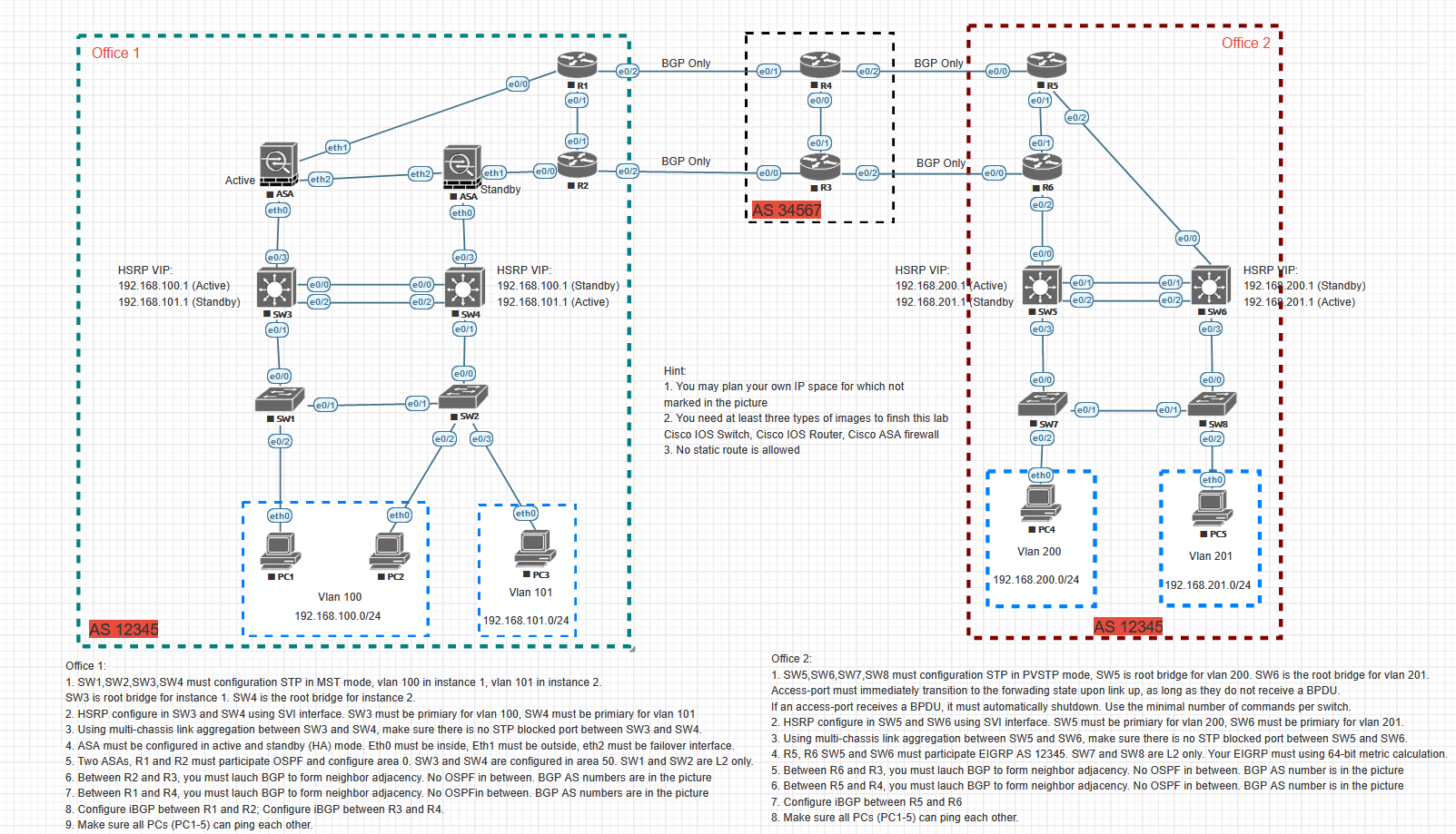
Office 2 1 Office 1 I I 1 10/1 BGP Only BGP Only e0/2 (e0/0 1 e0/0 R1 (e0/1 R4 (0/0 RS (20/1 1 1 1 1 1 1 1 1 e0/1 e0/1 . e0/1 1 1 (eth1 BGP Only 1 BGP Only eth2 eth1 e0/0 e0/2 (e0/0 e0/2 (20/0 Ceth2 R3 Standby Active S ASA (etho 1 1 1 1 ASA etho I I AS 34567 1 1 1 1 1 1 e0/0 1 (e0/3 (e0/0 e0/3) HSRP VIP: 192.168.100.1 (Active) 192.168.101.1 (Standby) 1 1 1 HSRP VIP: 1 192.168.100.1 (Standby) I 192.168.101.1 (Active) (e0/0 HSRP VIP: 192.168.200.1 Active) 192.168.201.1 Standby e0/1 0/1 e0/2 SWS HSRP YIP: 192.167 200.1 (Standby) 192.167.201.1 (Active) (e0/2 e0/2) SWB SW4 SW6 e0/1 e0/3 e0/3 1 1 1 (e0/0 (e0/0 (e0/0 1 1 1 e0/1 Hint 1. You may plan your own IP space for which not marked in the picture 2. You need at least three types of images to finsh this lab Cisco IOS Switch, Cisco IOS Router, Cisco ASA firewall 3. No static route is allowed e0/ e0/1 Swt SW2 1 SWT (e0/2 SW8 e0/2 e0/2 e012 e0/3 1 1 etho etho 1 1 1 1 1 (etho (etho) 1 etho 1 1 . PC4 PCS I 1 II 1 1 1 1 1 Vlan 200 1 Vlan 201 1 1 1 PC1 PC2 1 1 1 PG Vlan 101 II 192.168.200.0/24 1192.168.201.0/24 | Vlan 100 192.168.100.0/24 192.168.101.0/241 1 AS 12345 AS 12345 Office 1: 1. SW1,SW2, SW3,SW4 must configuration STP in MST mode, vlan 100 in instance 1, vlan 101 in instance 2 SW3 is root bridge for instance 1. SW4 is the root bridge for instance 2. 2. HSRP configure in SW3 and SW4 using SVI interface. SW3 must be primiary for vlan 100, SW4 must be primiary for vian 101 3. Using multi-chassis link aggregation between SW3 and SW4, make sure there is no STP blocked port between SW3 and SW 4. 4. ASA must be configured in active and standby (HA) mode. Etho must be inside, Eth1 must be outside, eth2 must be failover interface. 5. Two ASAS, R1 and R2 must participate OSPF and configure area 0. SW3 and SW4 are configured in area 50. SW1 and SW2 are L2 only 6. Between R2 and R3, you must lauch BGP to form neighbor adjacency. No OSPF in between. BGP AS numbers are in the picture 7. Between R1 and R4, you must lauch BGP to form neighbor adjacency. No OSPFin between. BGP AS numbers are in the picture 8. Configure iBGP between R1 and R2; Configure iBGP between R3 and R4. 9. Make sure all PCs (PC1-5) can ping each other. Office 2: 1. SW5, SW6, SW7,SW8 must configuration STP in PVSTP mode, SW5 is root bridge for vlan 200. SW6 is the root bridge for vlan 201. Access-port must immediately transition to the forwading state upon link up, as long as they do not receive a BPDU. If an access-port receives a BPDU, it must automatically shutdown. Use the minimal number of commands per switch. 2. HSRP configure in SW5 and SW6 using SVI interface. SW5 must be primiary for vlan 200, SW6 must be primiary for vlan 201. 3. Using multi-chassis link aggregation between SW5 and SW6, make sure there is no STP blocked port between SW5 and SW6. 4. R5, R6 SW5 and SW6 must participate EIGRP AS 12345. SW7 and SW8 are L2 only. Your EIGRP must using 64-bit metric calculation. 5. Between R6 and R3, you must lauch BGP to form neighbor adjacency. No OSPF in between. BGP AS number is in the picture 6. Between R5 and R4, you must lauch BGP to form neighbor adjacency. No OSPF in between. BGP AS number is in the picture 7. Configure IBGP between R5 and R6 8. Make sure all PCs (PC1-5) can ping each other Office 2 1 Office 1 I I 1 10/1 BGP Only BGP Only e0/2 (e0/0 1 e0/0 R1 (e0/1 R4 (0/0 RS (20/1 1 1 1 1 1 1 1 1 e0/1 e0/1 . e0/1 1 1 (eth1 BGP Only 1 BGP Only eth2 eth1 e0/0 e0/2 (e0/0 e0/2 (20/0 Ceth2 R3 Standby Active S ASA (etho 1 1 1 1 ASA etho I I AS 34567 1 1 1 1 1 1 e0/0 1 (e0/3 (e0/0 e0/3) HSRP VIP: 192.168.100.1 (Active) 192.168.101.1 (Standby) 1 1 1 HSRP VIP: 1 192.168.100.1 (Standby) I 192.168.101.1 (Active) (e0/0 HSRP VIP: 192.168.200.1 Active) 192.168.201.1 Standby e0/1 0/1 e0/2 SWS HSRP YIP: 192.167 200.1 (Standby) 192.167.201.1 (Active) (e0/2 e0/2) SWB SW4 SW6 e0/1 e0/3 e0/3 1 1 1 (e0/0 (e0/0 (e0/0 1 1 1 e0/1 Hint 1. You may plan your own IP space for which not marked in the picture 2. You need at least three types of images to finsh this lab Cisco IOS Switch, Cisco IOS Router, Cisco ASA firewall 3. No static route is allowed e0/ e0/1 Swt SW2 1 SWT (e0/2 SW8 e0/2 e0/2 e012 e0/3 1 1 etho etho 1 1 1 1 1 (etho (etho) 1 etho 1 1 . PC4 PCS I 1 II 1 1 1 1 1 Vlan 200 1 Vlan 201 1 1 1 PC1 PC2 1 1 1 PG Vlan 101 II 192.168.200.0/24 1192.168.201.0/24 | Vlan 100 192.168.100.0/24 192.168.101.0/241 1 AS 12345 AS 12345 Office 1: 1. SW1,SW2, SW3,SW4 must configuration STP in MST mode, vlan 100 in instance 1, vlan 101 in instance 2 SW3 is root bridge for instance 1. SW4 is the root bridge for instance 2. 2. HSRP configure in SW3 and SW4 using SVI interface. SW3 must be primiary for vlan 100, SW4 must be primiary for vian 101 3. Using multi-chassis link aggregation between SW3 and SW4, make sure there is no STP blocked port between SW3 and SW 4. 4. ASA must be configured in active and standby (HA) mode. Etho must be inside, Eth1 must be outside, eth2 must be failover interface. 5. Two ASAS, R1 and R2 must participate OSPF and configure area 0. SW3 and SW4 are configured in area 50. SW1 and SW2 are L2 only 6. Between R2 and R3, you must lauch BGP to form neighbor adjacency. No OSPF in between. BGP AS numbers are in the picture 7. Between R1 and R4, you must lauch BGP to form neighbor adjacency. No OSPFin between. BGP AS numbers are in the picture 8. Configure iBGP between R1 and R2; Configure iBGP between R3 and R4. 9. Make sure all PCs (PC1-5) can ping each other. Office 2: 1. SW5, SW6, SW7,SW8 must configuration STP in PVSTP mode, SW5 is root bridge for vlan 200. SW6 is the root bridge for vlan 201. Access-port must immediately transition to the forwading state upon link up, as long as they do not receive a BPDU. If an access-port receives a BPDU, it must automatically shutdown. Use the minimal number of commands per switch. 2. HSRP configure in SW5 and SW6 using SVI interface. SW5 must be primiary for vlan 200, SW6 must be primiary for vlan 201. 3. Using multi-chassis link aggregation between SW5 and SW6, make sure there is no STP blocked port between SW5 and SW6. 4. R5, R6 SW5 and SW6 must participate EIGRP AS 12345. SW7 and SW8 are L2 only. Your EIGRP must using 64-bit metric calculation. 5. Between R6 and R3, you must lauch BGP to form neighbor adjacency. No OSPF in between. BGP AS number is in the picture 6. Between R5 and R4, you must lauch BGP to form neighbor adjacency. No OSPF in between. BGP AS number is in the picture 7. Configure IBGP between R5 and R6 8. Make sure all PCs (PC1-5) can ping each other