OL-36 Series and Parallel Circuit Using PhET Simulation Tool Objective 1. Learn to build up series circuit and a parallel circuit with three resisters. 2.
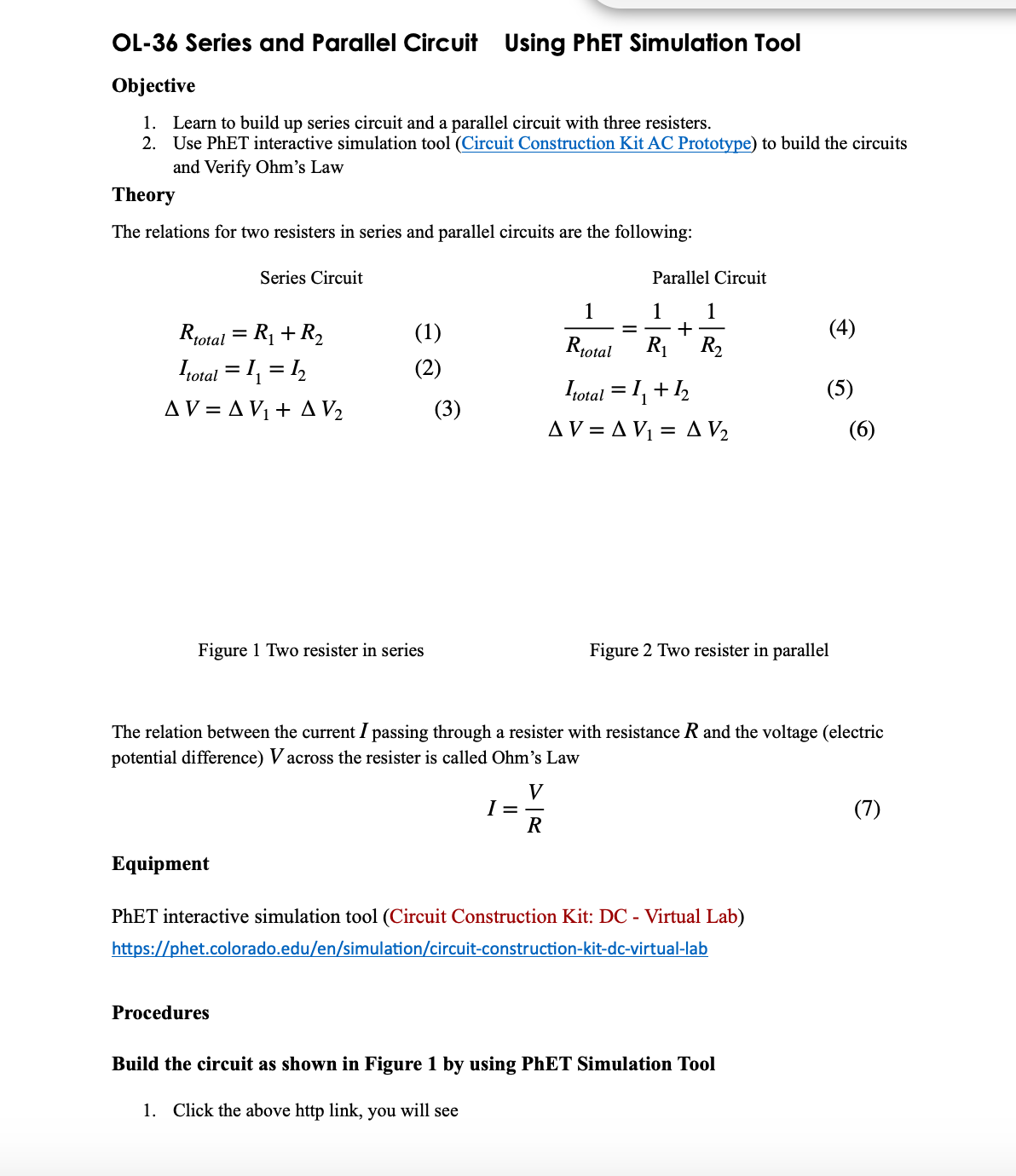
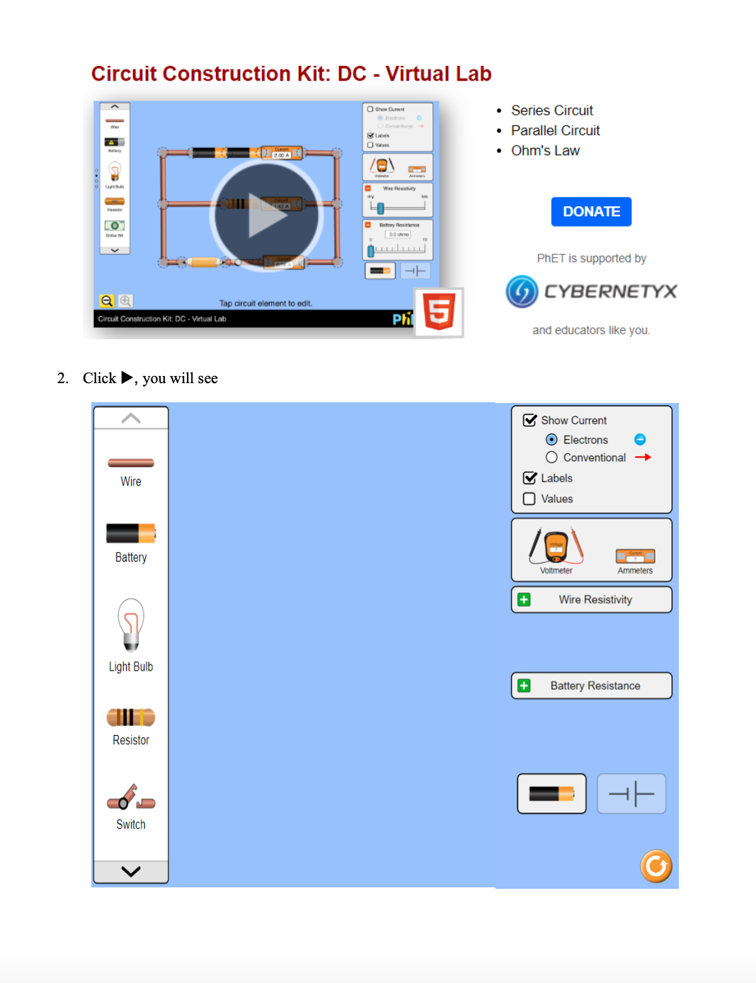
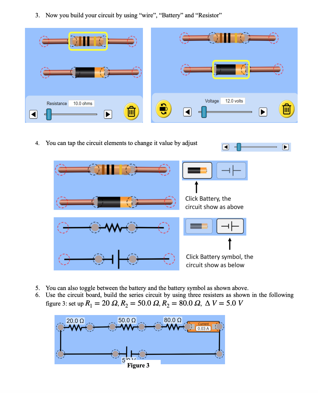
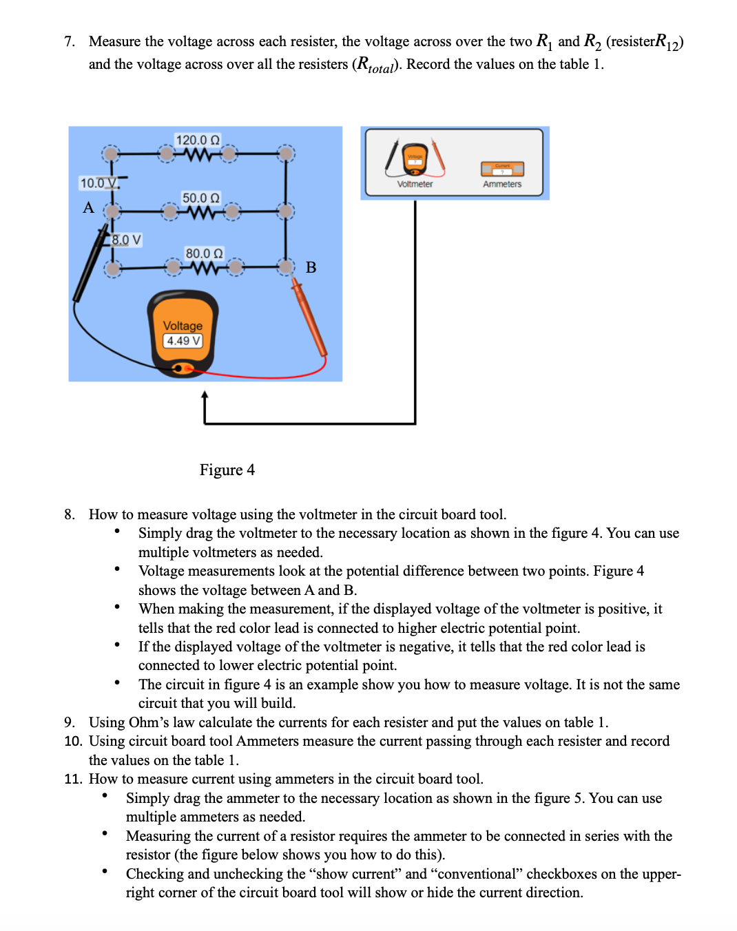
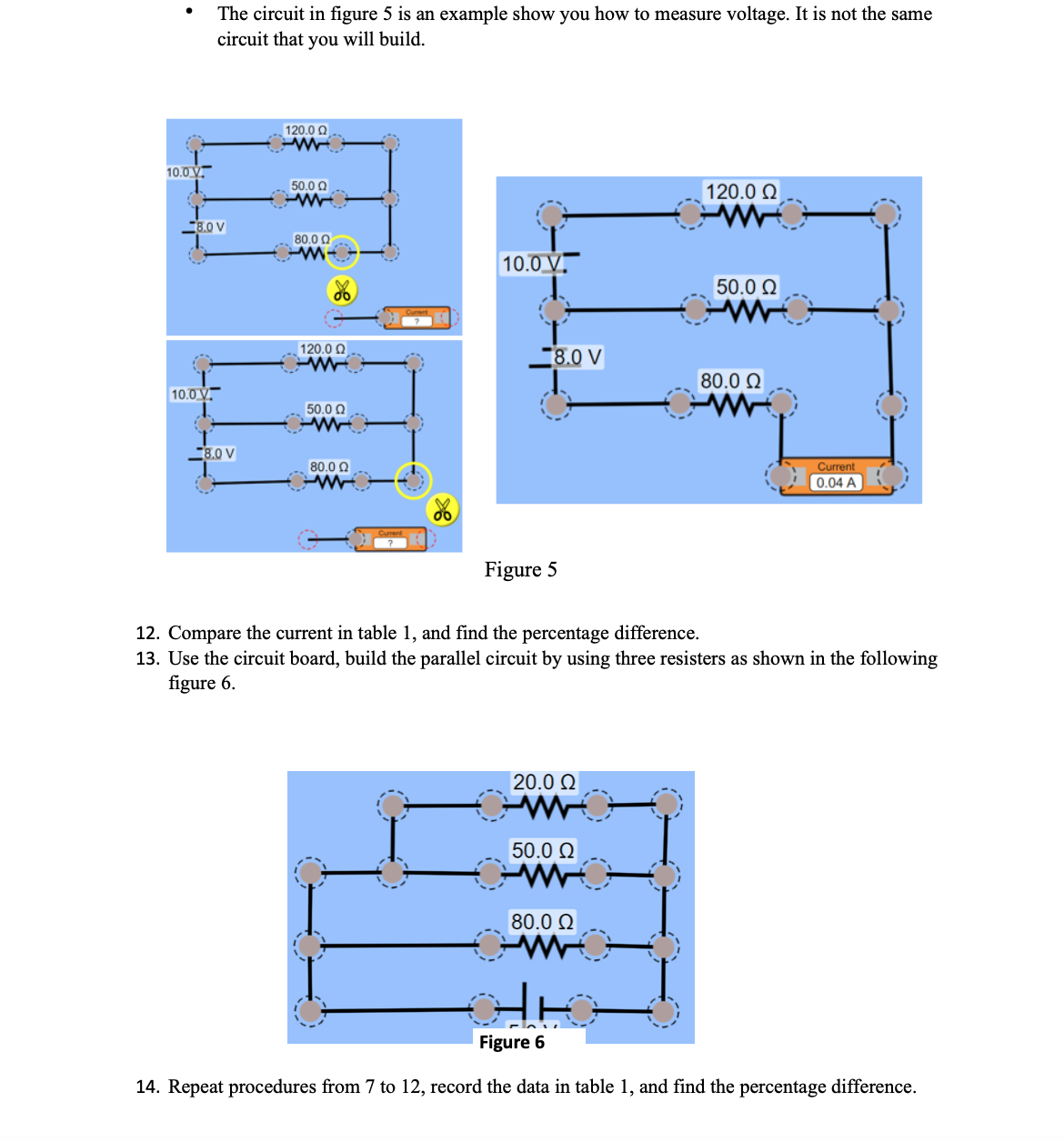
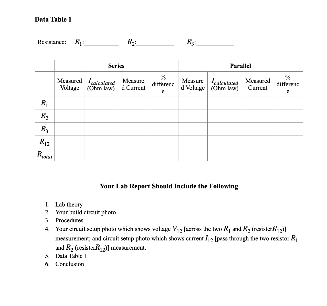
OL-36 Series and Parallel Circuit Using PhET Simulation Tool Objective 1. Learn to build up series circuit and a parallel circuit with three resisters. 2. Use PhET interactive simulation tool (Circuit Construction Kit AC Prototype) to build the circuits and Verify Ohm's Law Theory The relations for two resisters in series and parallel circuits are the following: Series Circuit Parallel Circuit 1 _ 1 + 1 (4) Rm\"! 2 R1+R2 (I) Rroml R1 R2 [total = II = 12 (2) 1mm! = I] + 12 (5) AV=AV1+AV2 (3) AV=AV1=AV2 (6) Figure 1 Two resister in series Figure 2 Two resister in parallel The relation between the current I passing through a resister with resistance R and the voltage (electric potential difference) Vacross the resister is called OhIn's Law 1:5 (7) Equipment PhET interactive simulation tool (Circuit Construction Kit: DC - Virtual Lab) httes:[/ehet.colorado.ed u/en/slmu laon/circuitconstruconkltdcvirtua |la b Procedures Build the circuit as shown in Figure 1 by using PhET Simulation Tool 1. Click the above http link, you will see Circuit Construction Kit: DC - Virtual Lab - Series Circuit I Parallel Circuit - Ohm's Law DONATE PhET is supported try 0 CYBERNETYX and educators like you. Light Bulb 4.. 3. Now you build your eimuit by using \"Wire\'1". Measure the voltage across each resister, the voltage across over the two R] and R2 (resisterRlz) and the voltage across over all the resisters (Rmmll- Record the values on the table 1. Figure 4 8. How to measure voltage using the voltmeter in the circuit board tool. " Simply drag the voltmeter to the necessary location as shown in the gure 4. You can use multiple voltmeters as needed. " Voltage measurements look at the potential difference between two points. Figure 4 shows the voltage between A and B. " When making the measurement, if the displayed voltage of the voltmeter is positive, it tells that the red color lead is connected to higher electric potential point. " If the displayed voltage of the voltmeter is negative, it tells that the red color lead is connected to lower electric potential point. The circuit in gure 4 is an example show you how to measure voltage. It is not the same circuit that you will build. 9. Using Ohm's law calculate the currents for each resister and put the values on table 1. 10. Using circuit board tool Ammeters measure the current passing through each resister and record the values on the table 1. 11. How to measure current using ammeters in the circuit board tool. " Simply drag the ammeter to the necessary location as shown in the figure 5. You can use multiple ammeters as needed. Measuring the current of a resistor requires the ammeter to be connected in series with the resistor (the figure below shows you how to do this). Checking and unchecking the \"show current\" and \"conventional" checkboxes on the upper- right corner of the circuit board tool will show or hide the current direction. The circuit in figure 5 is an example show you how to measure voltage. It is not the same circuit that you will build. 120.0 0 10.0 V. 50.0 0 120.0 0 80.0 0 10.0 V 50.0 0 120.0 0 18.0 V 80.0 0 10.0 V. 50.0 0 -80 V 80.0 0 Current 0.04 A Figure 5 12. Compare the current in table 1, and find the percentage difference. 13. Use the circuit board, build the parallel circuit by using three resisters as shown in the following figure 6. 20.0 0 50.0 0 80.0 0 Figure 6 14. Repeat procedures from 7 to 12, record the data in table 1, and find the percentage difference.Data Table 1 Resistance: RT: R2: R3: Series Parallel 0% Measured calculated Measure calculated Measured (Ohm law) d Current differenc Measure d Voltage (Ohm law) Current differenc Voltage e e R1 R2 R3 R 12 Rtotal Your Lab Report Should Include the Following 1. Lab theory 2. Your build circuit photo 3. Procedures 4. Your circuit setup photo which shows voltage V12 [across the two R, and R2 (resisterR12)] measurement; and circuit setup photo which shows current /12 [pass through the two resistor R] and R2 (resisterR12)] measurement. 5. Data Table 1 6. Conclusion
Step by Step Solution
There are 3 Steps involved in it
Step: 1
Get Instant Access to Expert-Tailored Solutions
See step-by-step solutions with expert insights and AI powered tools for academic success
Step: 2
Step: 3
Ace Your Homework with AI
Get the answers you need in no time with our AI-driven, step-by-step assistance