Question
The convection coefficient associated with the flowing gases is h = h1 = h2 = 80W/m 2 K, while the electrical resistance of the load
The convection coefficient associated with the flowing gases is h = h1 = h2 = 80W/m2K, while the electrical resistance of the load is R=4Ohm, T(infitie,1)=450C and a cold gas at T(infitie,2) =20C.
a) Sketch the equicalent Thermal circuit and determine the electric power generated by the module for the situation hwere the hot and cold gasses provide convective heating and cooling directly to the module (no heat sinks)
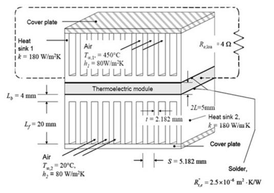
b) Two heat sinks (k=180W/mK) each with a base thickness of Lb= 4mm and fin Length Lf=20mm, are soldered to the upper and lower sides of the module. The fin spacing is 3mm, while the solder joints each have a thermal resistance of R"tc=2.5*10^-6 m^2K/W. Each heat sink has N= 11fins, so that t =2.182mm and S =5.182mm as determined from the requirements that W = (N-1)S + t and S-t = 3mm. Sketch the equivalent Thernam Circuit and determine the electric power generated by the module. Compare the electric power generated to your answer for part (a). Assume adiabatic fin tips and convection coefficients that are the same as in part (a)

Cover plate ! Heat i sink 1 ik = 180 W/m2K Air T= 450C h, = sow/m*K R 42 Thermoelectric module L, = 4 mm 2L=Smm =2.182 mm Heat sink 2, L,= 20 mm kF 180 W/mK Cover plate Air S= 5.182 mm T= 20C, h, = 80 W/m K Solder, %3D R, =2.5x10* m -K/W
Step by Step Solution
3.43 Rating (156 Votes )
There are 3 Steps involved in it
Step: 1
a a 9 Cuvert we Can write 8 TIT2 Here his given h3 ...
Get Instant Access to Expert-Tailored Solutions
See step-by-step solutions with expert insights and AI powered tools for academic success
Step: 2

Step: 3

Ace Your Homework with AI
Get the answers you need in no time with our AI-driven, step-by-step assistance
Get Started


