Answered step by step
Verified Expert Solution
Question
1 Approved Answer
Overview In this activity, you will use Packet Tracer to simulate the reconfiguration of devices in a reference network. To complete this activity, you


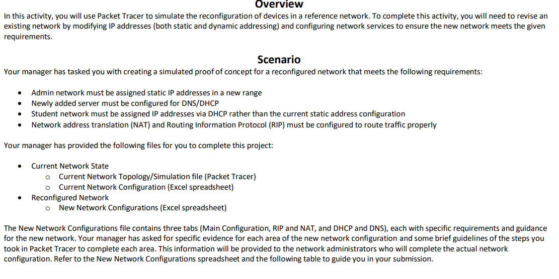
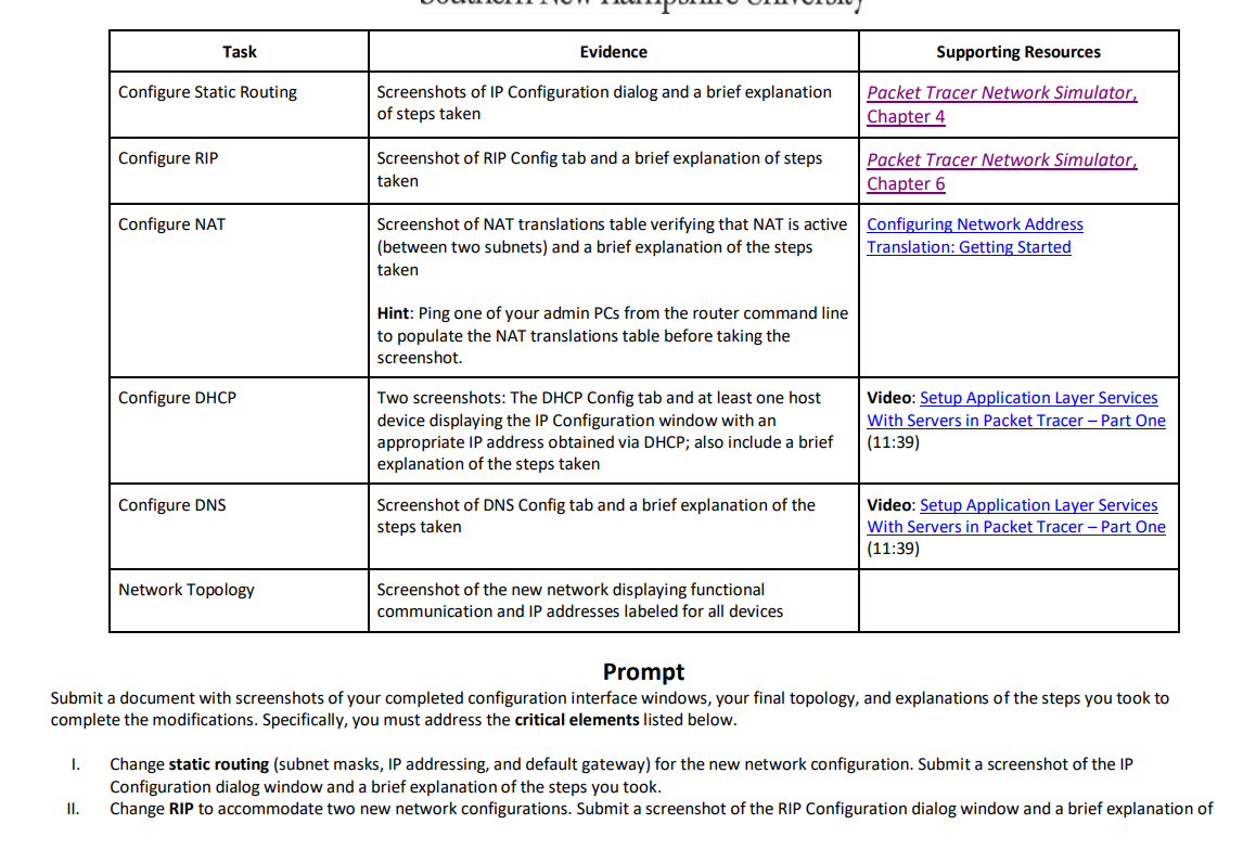
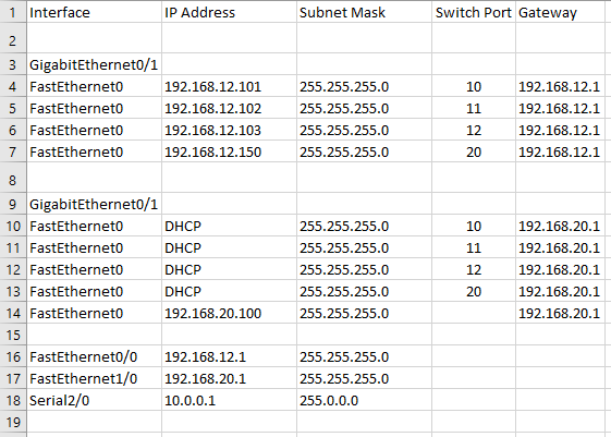
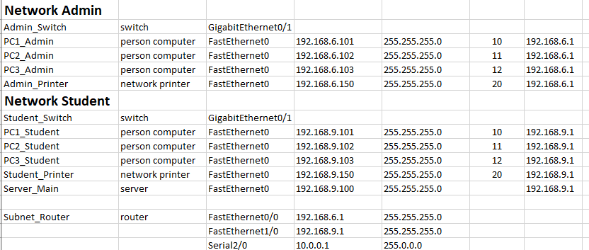
Overview In this activity, you will use Packet Tracer to simulate the reconfiguration of devices in a reference network. To complete this activity, you will need to revise an existing network by modifying IP addresses (both static and dynamic addressing) and configuring network services to ensure the new network meets the given requirements. Scenario Your manager has tasked you with creating a simulated proof of concept for a reconfigured network that meets the following requirements: Admin network must be assigned static IP addresses in a new range Newly added server must be configured for DNS/DHCP Student network must be assigned IP addresses via DHCP rather than the current static address configuration Network address translation (NAT) and Routing Information Protocol (RIP) must be configured to route traffic properly Your manager has provided the following files for you to complete this project: Current Network State O Current Network Topology/Simulation file (Packet Tracer) O Current Network Configuration (Excel spreadsheet) Reconfigured Network O New Network Configurations (Excel spreadsheet) The New Network Configurations file contains three tabs (Main Configuration, RIP and NAT, and DHCP and DNS), each with specific requirements and guidance for the new network. Your manager has asked for specific evidence for each area of the new network configuration and some brief guidelines of the steps you took in Packet Tracer to complete each area. This information will be provided to the network administrators who will complete the actual network configuration. Refer to the New Network Configurations spreadsheet and the following table to guide you in your submission. Task Configure Static Routing Configure RIP I. Configure NAT Configure DHCP Configure DNS Network Topology Evidence Screenshots of IP Configuration dialog and a brief explanation of steps taken Screenshot of RIP Config tab and a brief explanation of steps taken Screenshot of NAT translations table verifying that NAT is active (between two subnets) and a brief explanation of the steps taken Hint: Ping one of your admin PCs from the router command line to populate the NAT translations table before taking the screenshot. Two screenshots: The DHCP Config tab and at least one host device displaying the IP Configuration window with an appropriate IP address obtained via DHCP; also include a brief explanation of the steps taken Screenshot of DNS Config tab and a brief explanation of the steps taken Screenshot of the new network displaying functional communication and IP addresses labeled for all devices Supporting Resources Packet Tracer Network Simulator, Chapter 4 Packet Tracer Network Simulator, Chapter 6 Configuring Network Address Translation: Getting Started Video: Setup Application Layer Services With Servers in Packet Tracer - Part One (11:39) Video: Setup Application Layer Services With Servers in Packet Tracer - Part One (11:39) Prompt Submit a document with screenshots of your completed configuration interface windows, your final topology, and explanations of the steps you took to complete the modifications. Specifically, you must address the critical elements listed below. Change static routing (subnet masks, IP addressing, and default gateway) for the new network configuration. Submit a screenshot of the IP Configuration dialog window and a brief explanation of the steps you took. II. Change RIP to accommodate two new network configurations. Submit a screenshot of the RIP Configuration dialog window and a brief explanation of the steps you took. Configure NAT on the router. Submit a screenshot of the NAT translations table and a brief explanation of the steps you took. III. IV. Configure DHCP services. Submit two screenshots: The DHCP Config tab and at least one host device displaying the IP Configuration window with an appropriate IP address obtained via DHCP. Also include a brief explanation of the steps taken. V. Configure DNS for the server name and IP address. Submit a screenshot of the DNS Config tab and a brief explanation of the steps you took. VI. Label all devices and networks with the IP addresses. Submit a screenshot of the entire network topology. 1 Interface 2 3 GigabitEthernet0/1 4 FastEthernet0 5 FastEthernet0 6 FastEtherneto 7 FastEtherneto 8 9 GigabitEthernet0/1 10 FastEthernet0 11 FastEtherneto 12 FastEtherneto 13 FastEthernet0 14 FastEthernet0 IP Address 192.168.12.101 192.168.12.102 192.168.12.103 192.168.12.150 DHCP DHCP DHCP DHCP 192.168.20.100 15 16 FastEthernet0/0 192.168.12.1 17 FastEthernet1/0 192.168.20.1 18 Serial2/0 10.0.0.1 19 Subnet Mask 255.255.255.0 255.255.255.0 255.255.255.0 255.255.255.0 255.255.255.0 255.255.255.0 255.255.255.0 255.255.255.0 255.255.255.0 255.255.255.0 255.255.255.0 255.0.0.0 Switch Port Gateway 10 11 12 20 10 11 12 20 192.168.12.1 192.168.12.1 192.168.12.1 192.168.12.1 192.168.20.1 192.168.20.1 192.168.20.1 192.168.20.1 192.168.20.1 Network Admin Admin_Switch PC1_Admin PC2_Admin PC3_Admin Admin_Printer Network Student Student Switch PC1_Student PC2_Student PC3_Student Student_Printer Server_Main Subnet_Router switch GigabitEthernet0/1 person computer FastEthernet0 192.168.6.101 person computer FastEthernet0 192.168.6.102 person computer FastEtherneto 192.168.6.103 network printer FastEthernet0 192.168.6.150 switch GigabitEthernet0/1 person computer FastEthernet0 person computer FastEthernet0 person computer FastEthernet0 network printer FastEthernet0 server FastEthernet0 router 192.168.9.101 192.168.9.102 192.168.9.103 192.168.9.150 192.168.9.100 FastEthernet0/0 192.168.6.1 FastEthernet1/0 192.168.9.1 Serial2/0 10.0.0.1 255.255.255.0 255.255.255.0 255.255.255.0 255.255.255.0 255.255.255.0 255.255.255.0 255.255.255.0 255.255.255.0 255.255.255.0 255.255.255.0 255.255.255.0 255.0.0.0 10 11 12 20 10 11 12 20 192.168.6.1 192.168.6.1 192.168.6.1 192.168.6.1 192.168.9.1 192.168.9.1 192.168.9.1 192.168.9.1 192.168.9.1
Step by Step Solution
There are 3 Steps involved in it
Step: 1

Get Instant Access to Expert-Tailored Solutions
See step-by-step solutions with expert insights and AI powered tools for academic success
Step: 2

Step: 3

Ace Your Homework with AI
Get the answers you need in no time with our AI-driven, step-by-step assistance
Get Started


