

Answered step by step
Verified Expert Solution
Question
1 Approved Answer
Part 0 : Set Up the Topology and InitAddressing Table Objectives Part 1 : Configure and Apply a Named Standard ACL Part 2 : Configure
Part : Set Up the Topology and InitAddressing Table
Objectives
Part : Configure and Apply a Named Standard ACL
Part : Configure and Apply a Numbered Standard ACL
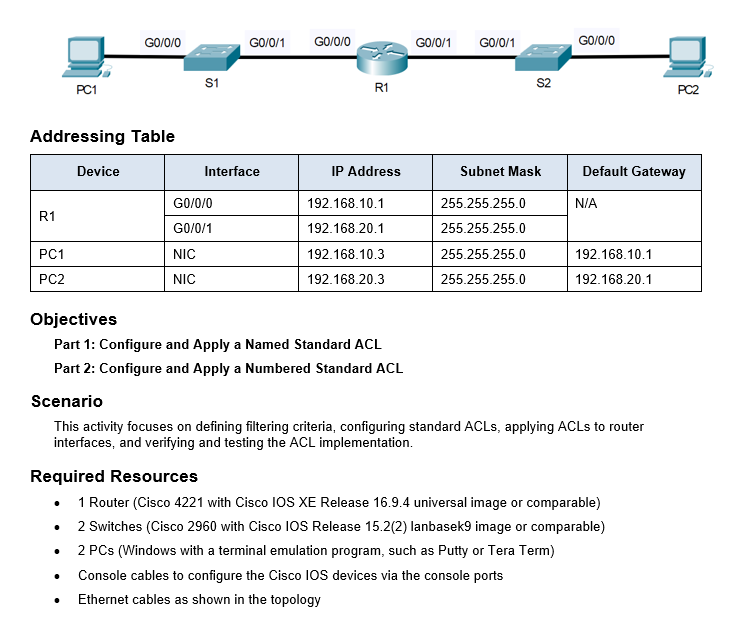
Scenario
This activity focuses on defining filtering criteria, configuring standard ACLs, applying ACLs to router
interfaces, and verifying and testing the ACL implementation.
Required Resources
Router Cisco with Cisco IOS XE Release universal image or comparable
Switches Cisco with Cisco IOS Release lanbasek image or comparable
PCs Windows with a terminal emulation program, such as Putty or Tera Term
Console cables to configure the Cisco IOS devices via the console ports
Ethernet cables as shown in the topologyialize Devices
Connect the device according to the given network topology.
Assign IP addresses according to the given addressing table.
Part : Configure and Apply a Named Standard ACL
Step : Verify connectivity before the ACL is configured and applied.
Both workstations should be able to ping to each other and all loopback interfaces.
Step : Configure a named standard ACL.
Open configuration window
a Configure an ACL on R named NetworkRestrictions. The ACL should only allow PC to connect with PC
Note: For scoring purposes, the ACL name is casesensitive and the statements must be in the same order as shown.
b Use the show accesslists command to verify the contents of the access list before applying it to an interface. Make sure you have not mistyped any IP addresses and that the statements are in the correct order.
R# show accesslists
Standard IP access list NetworkRestrictions
permit host
deny any
Step : Apply the named ACL.
a Apply the ACL outbound on the G interface.
Note: In an actual operational network, applying an access list to an active interface is not a good practice and should be avoided if possible.
Step : Verify the ACL configuration and application to the interface.
Open configuration window
Use the show accesslists command to verify the ACL configuration. Use the show run or show ip interface G command to verify that the ACL is applied correctly to the interface.
Step : Verify that the ACL is working properly.
PC should still be able to ping the PC
But what happens if you change the IP address of PC to any other available address in the same network. Will the ping still work. Why?
Repeat the show accesslists command to see the number of packets that matched each statement.
Close configuration window
Part : Configure and Apply a Numbered Standard ACL
Remove the named ACL configuration of Part from the router R
Rconfig# no ip accesslist standard NetworkRestrictions
Rconfig# interface G
Rconfigif# no ip accessgroup NetworkRestrictions out
Step : Verify connectivity before the ACL is configured and applied.
Both workstations should be able to ping to each other and all loopback interfaces.
Step : Configure and apply a numbered standard ACL on R
a Create an ACL using the number on R with a statement that denies access to the PC from the network.
Open configuration window
b By default, an access list denies all traffic that does not match any rules. Configure a statement to permit all other traffic.
c Before applying an access list to an interface to filter traffic, it is a best practice to review the contents of the access list, in order to verify that it will filter traffic as expected.
R# show accesslists
Standard IP access list
deny
permit any
Step : Apply the named ACL.
a For the ACL to actually filter traffic, it must be applied to some router operation. Apply the ACL by placing it for outbound traffic on the G interface. Note: In an actual operational network, it is not a good practice to apply an untested access list to an active interface.
Step : Verify the ACL configuration and application to the interface.
a Enter the show run or show ip interface Loopback command to verify the ACL placements.
Step : Verify that the ACL is working properly.
PC should not be able to ping the PC
Step by Step Solution
There are 3 Steps involved in it
Step: 1

Get Instant Access to Expert-Tailored Solutions
See step-by-step solutions with expert insights and AI powered tools for academic success
Step: 2

Step: 3
Ace Your Homework with AI
Get the answers you need in no time with our AI-driven, step-by-step assistance
Get Started
Database Systems On GPUs In Databases
Authors: Johns Paul ,Shengliang Lu ,Bingsheng He
1st Edition
1680838482, 978-1680838480