Question: Part 1: 7. Use the measured values and Figure 3 to use geometry of the experimental setup to calculate the angles Qmax m. 8. Note
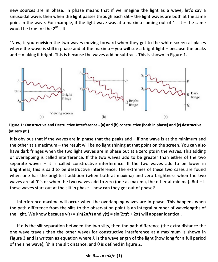
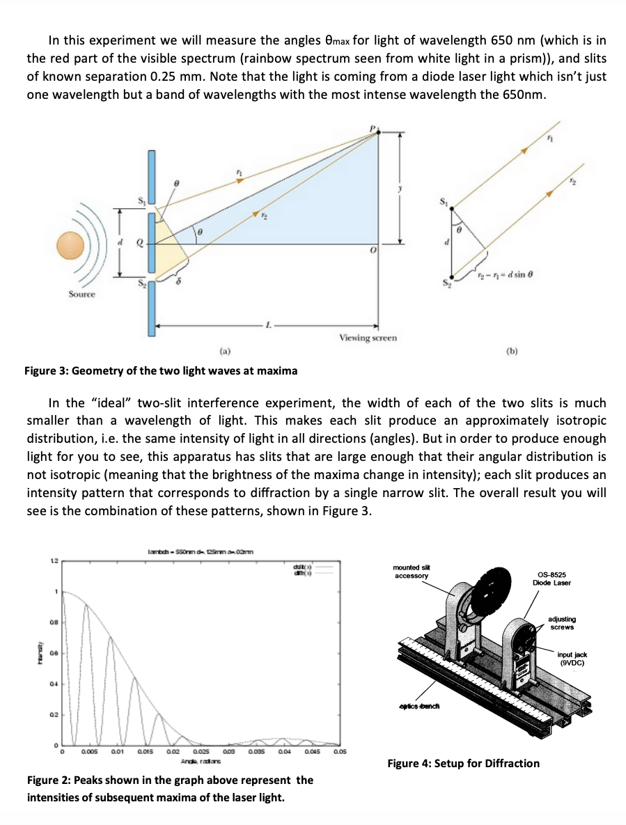
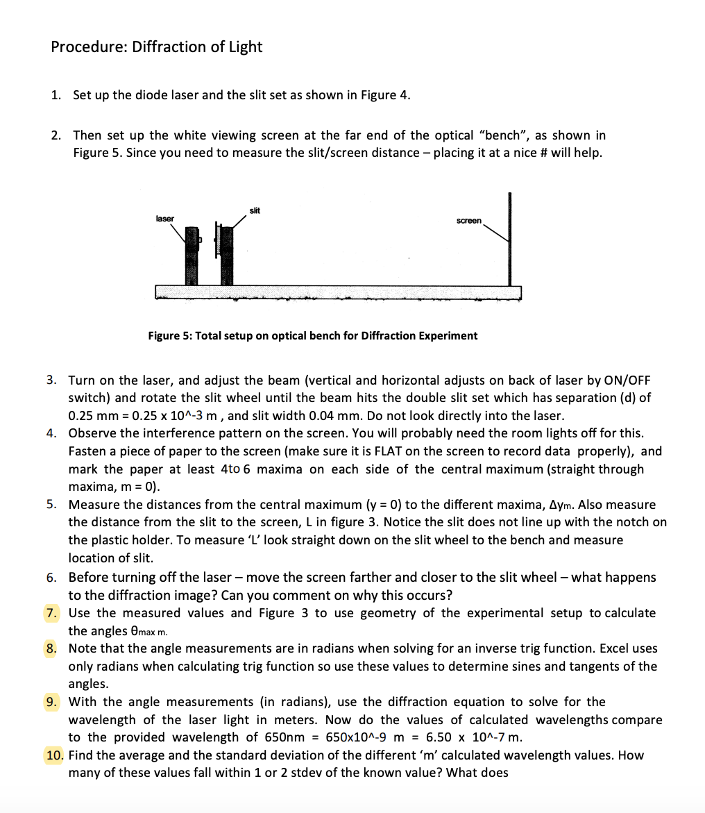
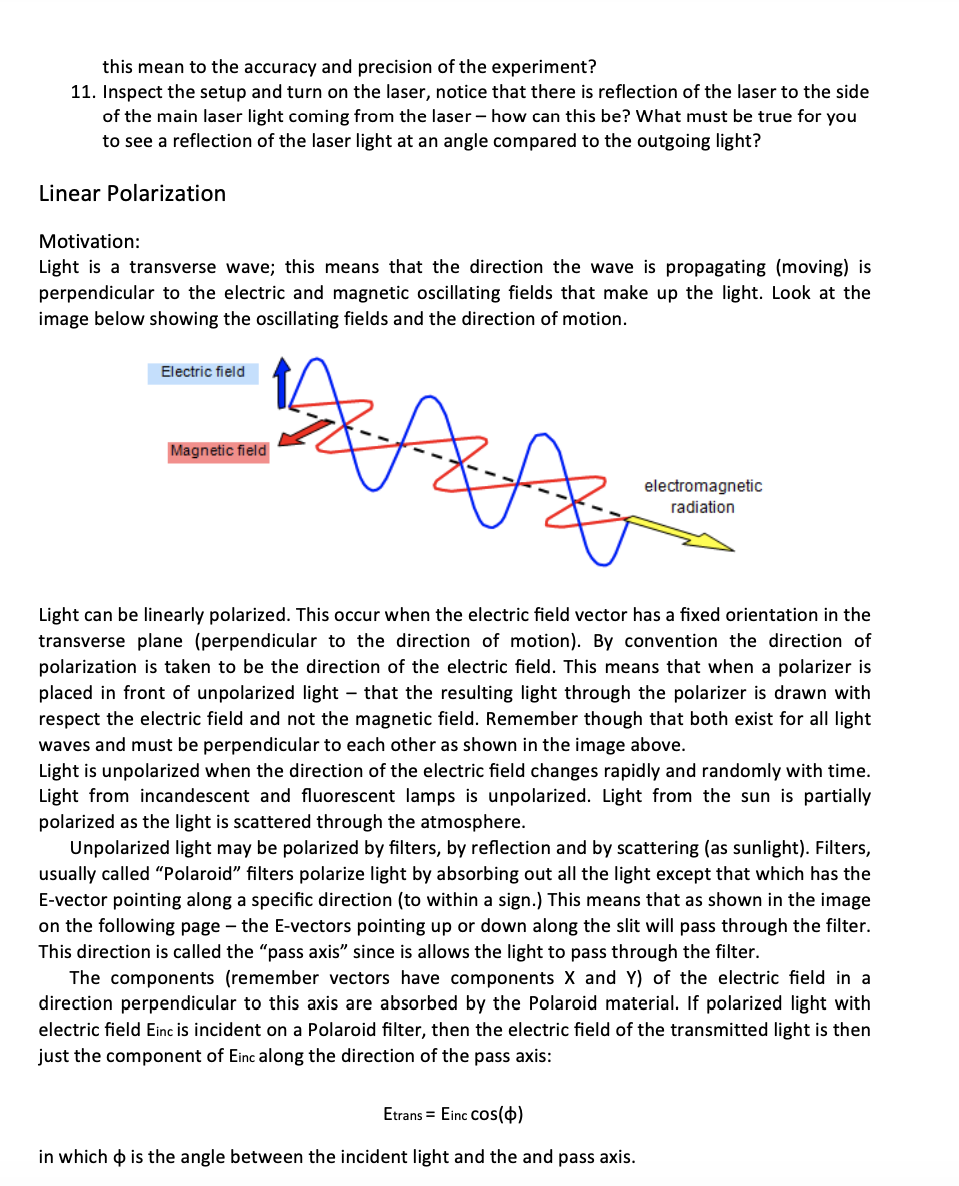
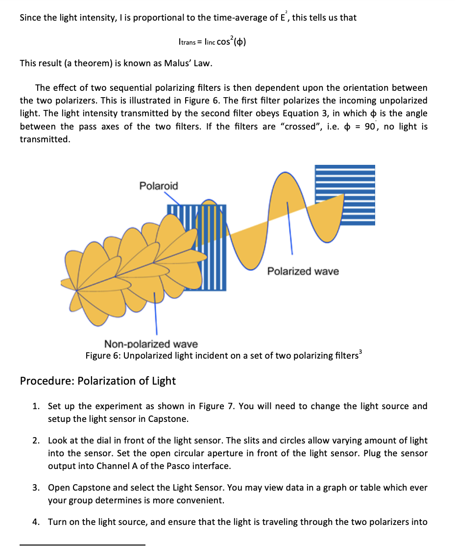
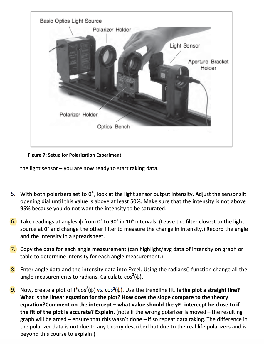
Part 1: 7. Use the measured values and Figure 3 to use geometry of the experimental setup to calculate the angles Qmax m. 8. Note that the angle measurements are in radians when solving for an inverse trig function. I Excel uses only radians when calculating trig mction so use these values to determine sines and tangents of the angles. 9. With the angle measurements (in radians), use the diffraction equation to solve for the wavelength of the laser light in meters. Now do the values of calculated wavelengths compare to the provided wavelength of 650nm = 650x10A-9 m = 6.50 x IDA-7 m. 10. Find the average and the standard deviation of the different 'm' calculated wavelength values. How many of these values fall within 1 or 2 stdex of the known value? What does Figure 5: Total setup on optical bench for Diffraction Experiment 5 this mean to the accuracy and precision of the experiment? 11. Inspect the setup and tum on the laser, notice that there is reection of the laser to the side of the main laser light coming from the laser how can this be? What must be true for you to see a reection of the laser light at an angle compared to the outgoing light? Part 2: 6. Take readings at angles (p 'om 0 to 90 in 10 intervals. (Leave the filter closest to the light source at 0 and change the other lter to measure the change in intensity.) Record the angle and the intensity in a spreadsheet. new sources are in phase. In phase means that if we imagine the light as a wave, let's say a sinusoidal wave, then when the light passes through each slit the light waves are both at the same point in the wave. For example, if the light wave was at a maxima coming out of 1 slit the same would be true for the 2"'1 slit. Now, if you envision the two waves moving forward when theyr get to the white screen at places where the wave is still in phase and at the maxima you will see a bright light because the peaks add making it bright. This is because the waves add or subtract. This is shown in Figure 1. I) I] BI ight Hi I 1 gr Dark R Iriuge' 0 Bright ' ing:- Q Vic-lying H Iu'n LI} \"1.1 fr: Figure 1: Constructive and Destructive Interference - {aland {b} constructive [both in phase} and {c} destructive [at zero th It is obvious that if the waves are in phase that the peaks add if one wave is at the minimum and the other at a maximum the result will be no light shining at that point on the screen. You can also have dark fringes when the two light waves are in phase but at a zero pts in the waves. This adding or overlapping is called interference. If the two waves add to be greater than either of the two separate waves it is called constructive interference. If the two waves add to be lower in brightness, this is said to be destructive interference. The extremes of these two cases are found when one has the brightest addition [when both at maximal and zero brightness when the two waves are at 'O's or when the two waves add to zero [one at maxima, the other at minimal. But if these waves start out at the slit in phase how can they get out of phase? Interference maxima will occur when the overlapping waves are in phase. This happens when the path difference from the slits to the observation point is an integral number of wavelengths of the light. We know because yit) = sianJ-rft) and t) = sinf2n + 211) will appear identical. If d is the slit separation between the two slits, then the path difference (the extra distance the one wave travels than the other wave] for constructive interference at a maximum is shown in Figure 3 and is written as equation where A is the wavelength of the light {how long for a full period of the sine wave), 'd' is the slit distance, and B is defined in figure 2. sin emax= [TIA/d {1] In this experiment we will measure the angles 0max for light of wavelength 650 nm (which is in the red part of the visible spectrum (rainbow spectrum seen from white light in a prism)), and slits of known separation 0.25 mm. Note that the light is coming from a diode laser light which isn't just one wavelength but a band of wavelengths with the most intense wavelength the 650nm. O 2- n = dsin 0 S. Source Viewing screen (a) (b ) Figure 3: Geometry of the two light waves at maxima In the "ideal" two-slit interference experiment, the width of each of the two slits is much smaller than a wavelength of light. This makes each slit produce an approximately isotropic distribution, i.e. the same intensity of light in all directions (angles). But in order to produce enough light for you to see, this apparatus has slits that are large enough that their angular distribution is not isotropic (meaning that the brightness of the maxima change in intensity); each slit produces an intensity pattern that corresponds to diffraction by a single narrow slit. The overall result you will see is the combination of these patterns, shown in Figure 3 lambch - 560rm d- 125mm 8-.03min mounted s accessory OS-8525 Diode Laser adjusting screws Handty 06 input jack (9VDC) 04 optics bench 0.005 Q01 0.015 Q.02 0.025 Q03 0.035 Q04 0.045 0.05 Figure 4: Setup for Diffraction Figure 2: Peaks shown in the graph above represent the intensities of subsequent maxima of the laser light.Procedure: Diffraction of Light 1. 2. 10. Set up the diode laser and the slit set as shown in Figure 4. Then set up the white viewing screen at the far end of the optical "bench\this mean to the accuracy and precision of the experiment? 11. Inspect the setup and turn on the laser, notice that there is reflection of the laser to the side of the main laser light coming from the laser - how can this be? What must be true for you to see a reflection of the laser light at an angle compared to the outgoing light? Linear Polarization Motivation: Light is a transverse wave; this means that the direction the wave is propagating (moving) is perpendicular to the electric and magnetic oscillating fields that make up the light. Look at the image below showing the oscillating fields and the direction of motion. Electric field Magnetic field electromagnetic radiation Light can be linearly polarized. This occur when the electric field vector has a fixed orientation in the transverse plane (perpendicular to the direction of motion). By convention the direction of polarization is taken to be the direction of the electric field. This means that when a polarizer is placed in front of unpolarized light - that the resulting light through the polarizer is drawn with respect the electric field and not the magnetic field. Remember though that both exist for all light waves and must be perpendicular to each other as shown in the image above. Light is unpolarized when the direction of the electric field changes rapidly and randomly with time. Light from incandescent and fluorescent lamps is unpolarized. Light from the sun is partially polarized as the light is scattered through the atmosphere Unpolarized light may be polarized by filters, by reflection and by scattering (as sunlight). Filters, usually called "Polaroid" filters polarize light by absorbing out all the light except that which has the E-vector pointing along a specific direction (to within a sign.) This means that as shown in the image on the following page - the E-vectors pointing up or down along the slit will pass through the filter. This direction is called the "pass axis" since is allows the light to pass through the filter. The components (remember vectors have components X and Y) of the electric field in a direction perpendicular to this axis are absorbed by the Polaroid material. If polarized light with electric field Einc is incident on a Polaroid filter, then the electric field of the transmitted light is then just the component of Einc along the direction of the pass axis: Etrans = Einc cos(d) in which o is the angle between the incident light and the and pass axis.Since the light intensity, I is proportional to the time-average of E , this tells us that Itrans = linc cos () This result (a theorem) is known as Malus' Law. The effect of two sequential polarizing filters is then dependent upon the orientation between the two polarizers. This is illustrated in Figure 6. The first filter polarizes the incoming unpolarized light. The light intensity transmitted by the second filter obeys Equation 3, in which o is the angle between the pass axes of the two filters. If the filters are "crossed", i.e. o = 90, no light is transmitted. Polaroid Polarized wave Non-polarized wave Figure 6: Unpolarized light incident on a set of two polarizing filters Procedure: Polarization of Light 1. Set up the experiment as shown in Figure 7. You will need to change the light source and setup the light sensor in Capstone. 2. Look at the dial in front of the light sensor. The slits and circles allow varying amount of light into the sensor. Set the open circular aperture in front of the light sensor. Plug the sensor output into Channel A of the Pasco interface. 3. Open Capstone and select the Light Sensor. You may view data in a graph or table which ever your group determines is more convenient. 4. Turn on the light source, and ensure that the light is traveling through the two polarizers intoBasic Optics Light Source Polarizer Holder Light Sensor Aperture Bracket Holder Polarizer Holder Optics Bench Figure 7: Setup for Polarization Experiment the light sensor - you are now ready to start taking data. 5. With both polarizers set to 0', look at the light sensor output intensity. Adjust the sensor slit opening dial until this value is above at least 50%. Make sure that the intensity is not above 95% because you do not want the intensity to be saturated. 6. Take readings at angles o from 0' to 90 in 10 intervals. (Leave the filter closest to the light source at 0' and change the other filter to measure the change in intensity.) Record the angle and the intensity in a spreadsheet. 7. Copy the data for each angle measurement (can highlight/avg data of intensity on graph or table to determine intensity for each angle measurement.) 8. Enter angle data and the intensity data into Excel. Using the radians() function change all the angle measurements to radians. Calculate cos () 9. Now, create a plot of I*cos () vs. cos?(). Use the trendline fit. Is the plot a straight line? What is the linear equation for the plot? How does the slope compare to the theory equation?Comment on the intercept - what value should the yF intercept be close to if the fit of the plot is accurate? Explain. (note if the wrong polarizer is moved - the resulting graph will be arced - ensure that this wasn't done - if so repeat data taking. The difference in the polarizer data is not due to any theory described but due to the real life polarizers and is beyond this course to explain.)
Step by Step Solution
There are 3 Steps involved in it

Get step-by-step solutions from verified subject matter experts


