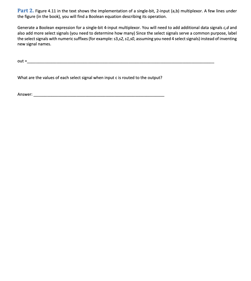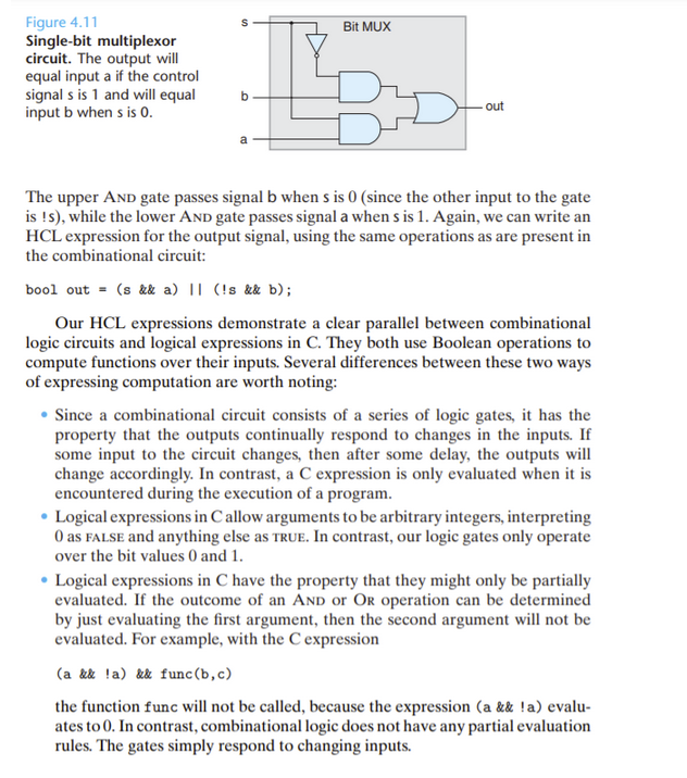

Part 2. Figure 4.11 in the text shows the implementation of a single-bit, 2-input (a,b) multiplexor. A few lines under the figure in the book), you will find a Boolean equation describing its operation. Generate a Boolean expression for a single-bit 4-input multiplexor. You will need to add additional data signals cd and also add more select signals (you need to determine how many) Since the select signals serve a common purpose, label the select signals with numeric suffixes (for example: 53,52, 51,50, assuming you need 4 select signals) instead of inventing new signal names. out What are the values of each select signal when input c is routed to the output? Answer: Bit MUX Figure 4.11 Single-bit multiplexor circuit. The output will equal input a if the control signals is 1 and will equal input b when s is 0. . out The upper And gate passes signal b when s is 0 (since the other input to the gate is !), while the lower AND gate passes signal a when sis 1. Again, we can write an HCL expression for the output signal, using the same operations as are present in the combinational circuit: bool out = (s && a) || (!s && b); Our HCL expressions demonstrate a clear parallel between combinational logic circuits and logical expressions in C. They both use Boolean operations to compute functions over their inputs. Several differences between these two ways of expressing computation are worth noting: Since a combinational circuit consists of a series of logic gates, it has the property that the outputs continually respond to changes in the inputs. If some input to the circuit changes, then after some delay, the outputs will change accordingly. In contrast, a C expression is only evaluated when it is encountered during the execution of a program. Logical expressions in Callow arguments to be arbitrary integers, interpreting O as FALSE and anything else as TRUE. In contrast, our logic gates only operate over the bit values 0 and 1. Logical expressions in C have the property that they might only be partially evaluated. If the outcome of an AND or Or operation can be determined by just evaluating the first argument, then the second argument will not be evaluated. For example, with the expression (a && !a) && func(b,c) the function func will not be called, because the expression (a && !a) evalu- ates to 0. In contrast, combinational logic does not have any partial evaluation rules. The gates simply respond to changing inputs


