Answered step by step
Verified Expert Solution
Question
1 Approved Answer
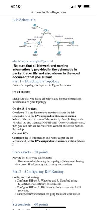
6:40 Lab Schematic (this moodle.tbcollege.com 4161630 is only an example) Figure 1-1 *Be sure that all Network and naming information is provided in the

6:40 Lab Schematic (this moodle.tbcollege.com 4161630 is only an example) Figure 1-1 *Be sure that all Network and naming information is provided in the schematic in packet tracer file and also shown in the word document that you submit. Part 1 - Building the Topology Create the topology as depicted in Figure 1-1 above. On all objects: Make sure that you name all objects and include the network information on your topology 0 MAN On the 2811 routers: Configure IP's on the network interfaces as per the lab schematic (Use the IP's assigned in Resources section below). You need to turn off the router by first clicking on the Physical tab and then add NM-4E card. Once you add the card, then you can turn on the router and connect one of the ports to the laptop. On each PC: Configure the IP information and Name as per the lab schematic (Use the IP's assigned in Resources section below) 0 Screenshots-20 points Provide the following screenshots: 1. One screenshot showing the topology (Schematic) having the correct IP addressing and naming conventions Part 2 - Configuring RIP Routing Config and test routing: Configure RIP on R_Waterloo and R_Stratford using R_Kitchener as gateway of last resort. 2 Configure RIP on R_Kitchener to both remote site LAN networks. Ensure each workstation can ping the other workstation Screenshots - 60 points
Step by Step Solution
★★★★★
3.43 Rating (153 Votes )
There are 3 Steps involved in it
Step: 1

Get Instant Access to Expert-Tailored Solutions
See step-by-step solutions with expert insights and AI powered tools for academic success
Step: 2

Step: 3

Ace Your Homework with AI
Get the answers you need in no time with our AI-driven, step-by-step assistance
Get Started


