Answered step by step
Verified Expert Solution
Question
1 Approved Answer
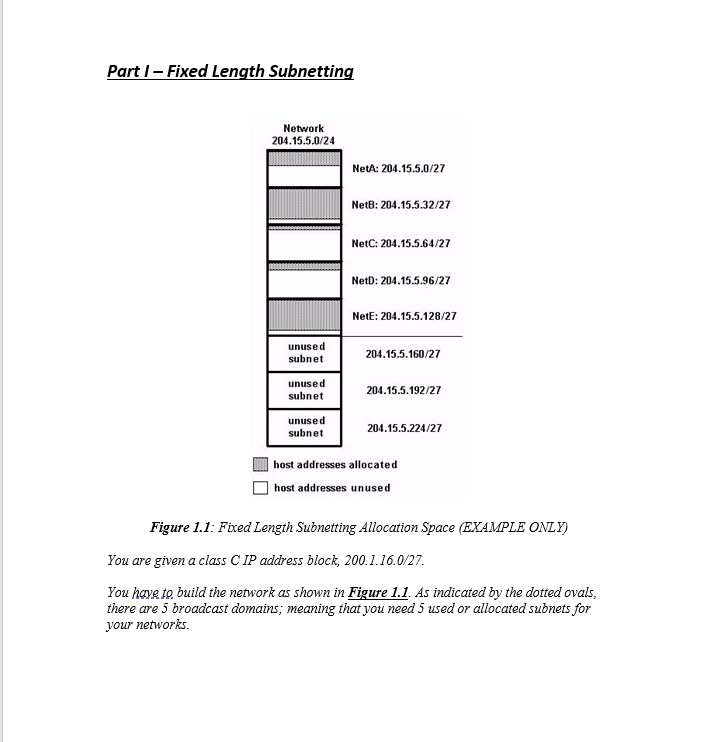
Part I - Fixed Length Subnetting Network 204.15.5.0/24 NetA: 204.15.5.0/27 NetB: 204.15.5.32/27 NetC: 204.15.5.64/27 NetD: 204.15.5.96/27 NetE: 204.15.5.128/27 unused 204.15.5.160/27 subnet unused 204.15.5.192/27 subnet


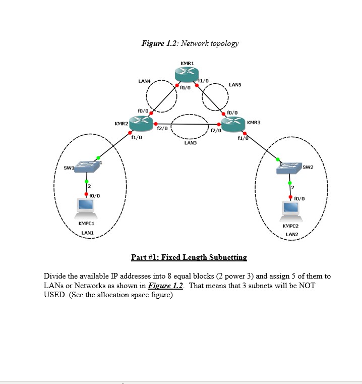
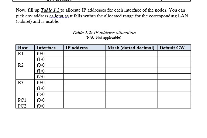
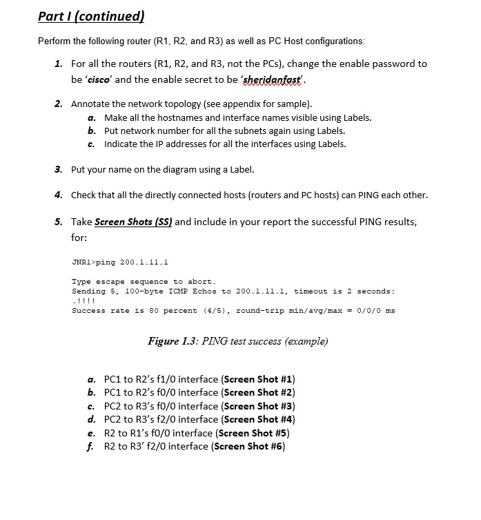
Part I - Fixed Length Subnetting Network 204.15.5.0/24 NetA: 204.15.5.0/27 NetB: 204.15.5.32/27 NetC: 204.15.5.64/27 NetD: 204.15.5.96/27 NetE: 204.15.5.128/27 unused 204.15.5.160/27 subnet unused 204.15.5.192/27 subnet unused subnet 204.15.5.224/27 host addresses allocated host addresses unused Figure 1.1: Fixed Length Subnetting Allocation Space (EXAMPLE ONLY) You are given a class C IP address block, 200.1.16.0/27. You have to build the network as shown in Figure 1.1. As indicated by the dotted ovals, there are 5 broadcast domains; meaning that you need 5 used or allocated subnets for your networks. SW1 2 10/0 KMPC1 LAN1 Figure 1.2: Network topology KMR1 LAN4 11/0 f0/0 LANS KMR2 10/0 f1/0 10/0 KMR3 12/0 12/0 f1/0 LAN3 10/0 KMPC2 LAN2 SW2 Part #1: Fixed Length Subnetting Divide the available IP addresses into 8 equal blocks (2 power 3) and assign 5 of them to LANs or Networks as shown in Figure 1.2. That means that 3 subnets will be NOT USED. (See the allocation space figure) Now, fill up Table 1.2 to allocate IP addresses for each interface of the nodes. You can pick any address as long as it falls within the allocated range for the corresponding LAN (subnet) and is usable. Table 1.2: IP address allocation (N/A- Not applicable) Host Interface IP address R1 f0/0 f1/0 R2 f0/0 f1/0 2/0 R3 f0/0 f1/0 2/0 PC1 f0/0 PC2 0/0 Mask (dotted decimal) Default GW Part I (continued) Perform the following router (R1, R2, and R3) as well as PC Host configurations: 1. For all the routers (R1, R2, and R3, not the PCs), change the enable password to be 'cisco' and the enable secret to be 'sheridanfast. 2. Annotate the network topology (see appendix for sample). a. Make all the hostnames and interface names visible using Labels. b. Put network number for all the subnets again using Labels. c. Indicate the IP addresses for all the interfaces using Labels. 3. Put your name on the diagram using a Label. 4. Check that all the directly connected hosts (routers and PC hosts) can PING each other. 5. Take Screen Shots (SS) and include in your report the successful PING results, for: JNR1>ping 200.1.11.1 Type escape sequence to abort. Sending 5, 100-byte ICMP Echos to 200.1.11.1, timeout is 2 seconds: .!!!! Success rate is 80 percent (4/5), round-trip min/avg/max = 0/0/0 ms Figure 1.3: PING test success (example) a. PC1 to R2's f1/0 interface (Screen Shot #1) b. PC1 to R2's f0/0 interface (Screen Shot #2) c. PC2 to R3's f0/0 interface (Screen Shot #3) d. PC2 to R3's f2/0 interface (Screen Shot #4) e. R2 to R1's f0/0 interface (Screen Shot #5) f. R2 to R3' f2/0 interface (Screen Shot #6)
Step by Step Solution
There are 3 Steps involved in it
Step: 1

Get Instant Access to Expert-Tailored Solutions
See step-by-step solutions with expert insights and AI powered tools for academic success
Step: 2

Step: 3

Ace Your Homework with AI
Get the answers you need in no time with our AI-driven, step-by-step assistance
Get Started


