

Answered step by step
Verified Expert Solution
Question
1 Approved Answer
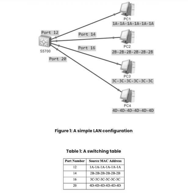
PC1 1A-1A-1A-1A-1A-1A Port 12 Port 14 Port 16 S5700 Port 20 PC2 2B-2B-2B-2B-2B-2B PC3 30-3C-30-30-3C-30 PC4 4D-4D-4D-4D-4D-4D Figure 1: A simple LAN configuration Table 1:
Step by Step Solution
There are 3 Steps involved in it
Step: 1

Get Instant Access to Expert-Tailored Solutions
See step-by-step solutions with expert insights and AI powered tools for academic success
Step: 2

Step: 3
Ace Your Homework with AI
Get the answers you need in no time with our AI-driven, step-by-step assistance
Get Started
Main Memory Database Systems
Authors: Frans Faerber, Alfons Kemper, Per-Åke Alfons
1st Edition
1680833243, 978-1680833249