Answered step by step
Verified Expert Solution
Question
1 Approved Answer
PHY 242 - Laboratory Force on q by q =7.69 x 10 N Force on q by q2 7.69 x 10⁶ N LABORATORY 3:
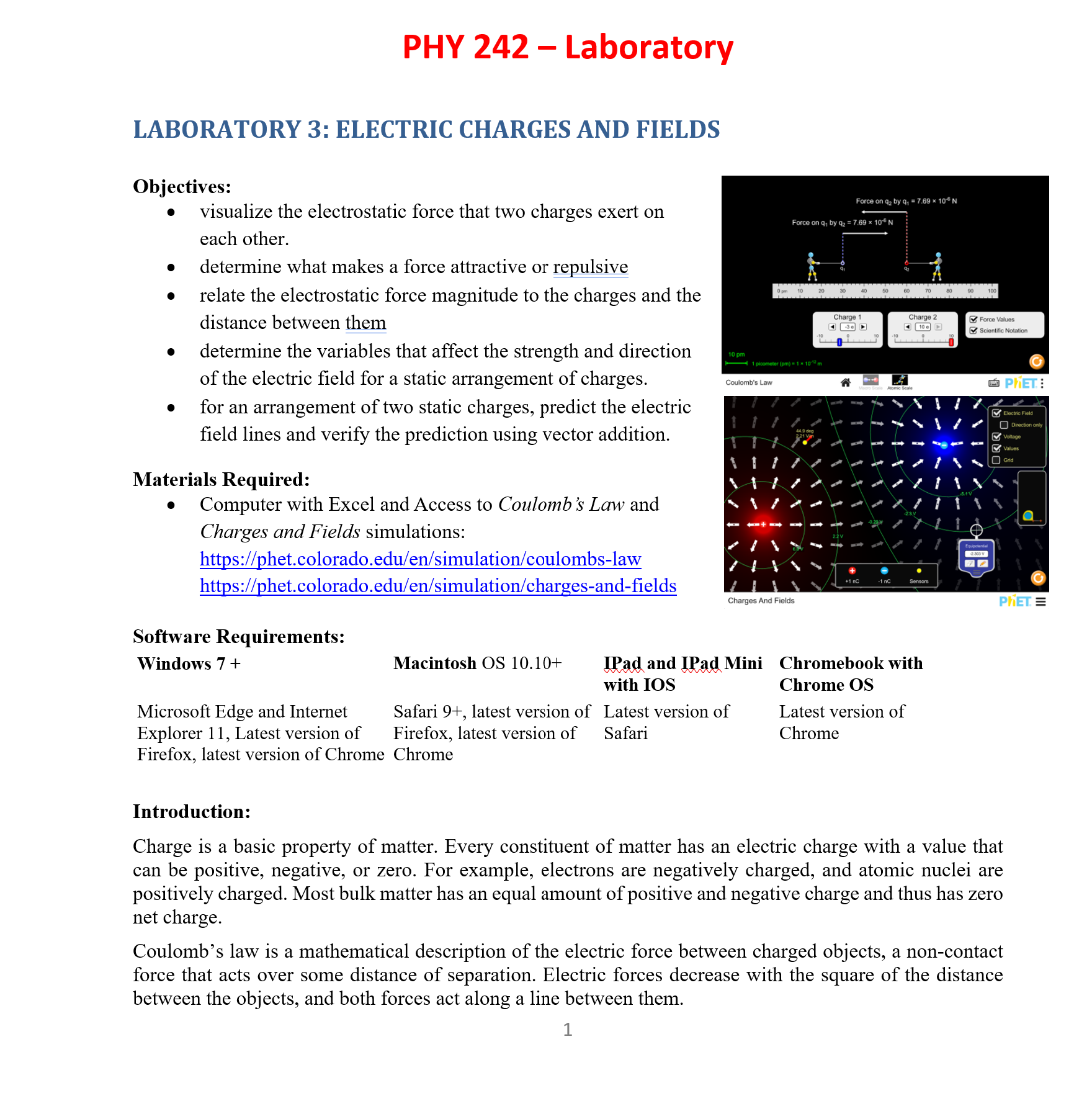
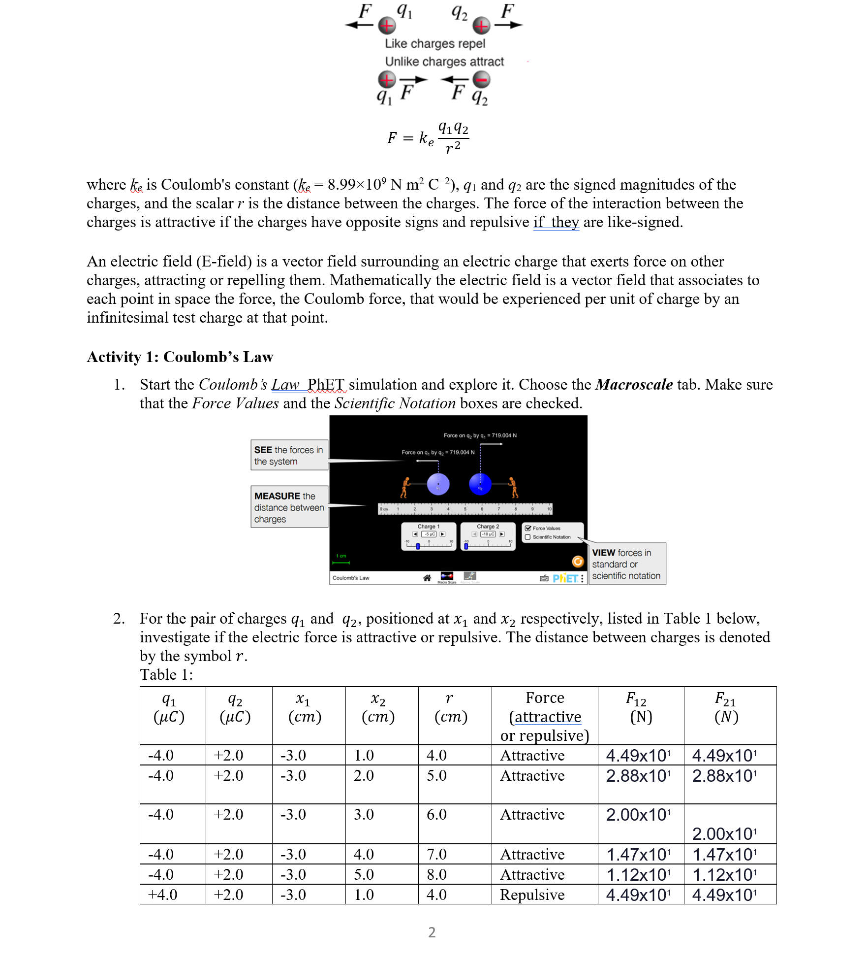
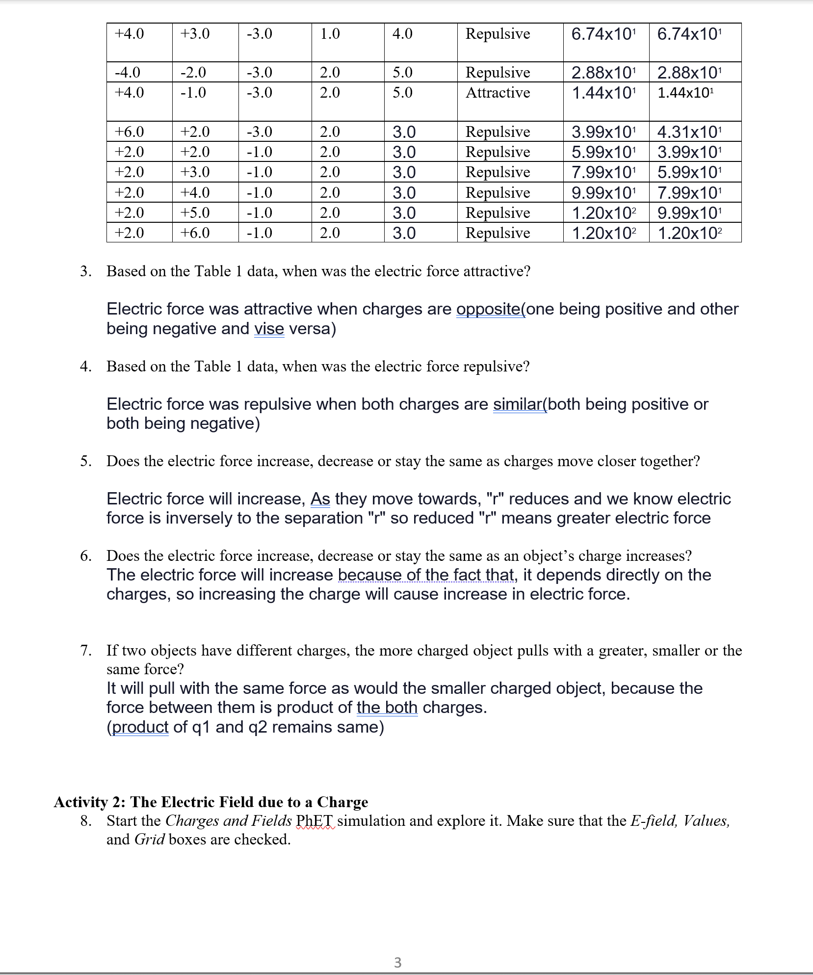
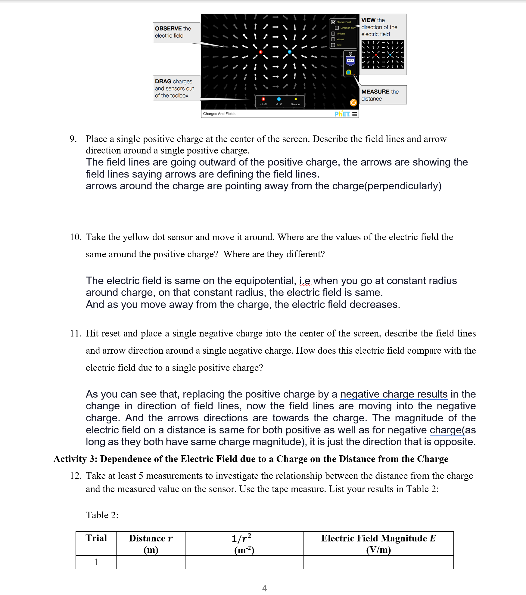
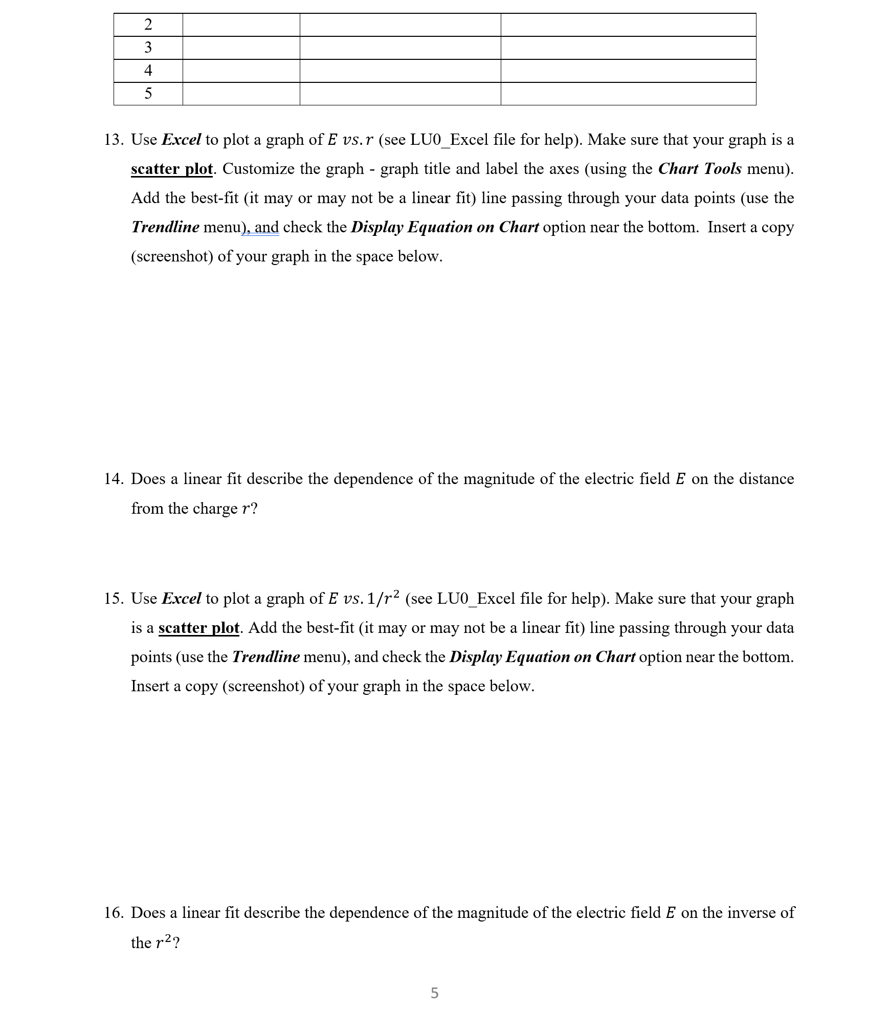
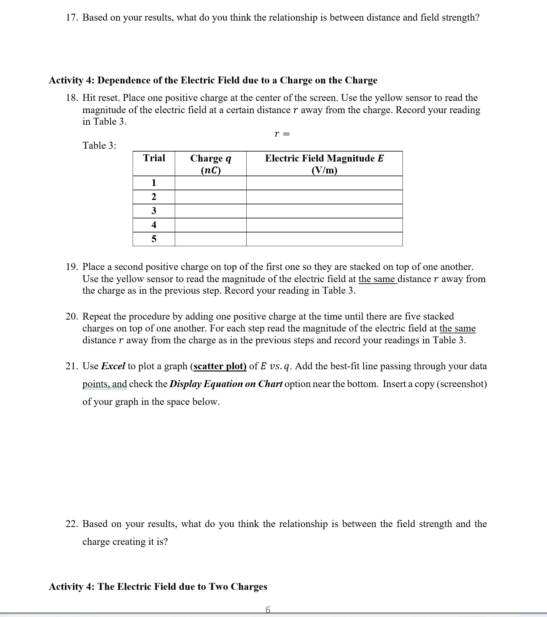
PHY 242 - Laboratory Force on q by q =7.69 x 10 N Force on q by q2 7.69 x 10⁶ N LABORATORY 3: ELECTRIC CHARGES AND FIELDS Objectives: visualize the electrostatic force that two charges exert on each other. determine what makes a force attractive or repulsive relate the electrostatic force magnitude to the charges and the distance between them determine the variables that affect the strength and direction of the electric field for a static arrangement of charges. for an arrangement of two static charges, predict the electric field lines and verify the prediction using vector addition. Materials Required: Computer with Excel and Access to Coulomb's Law and Charges and Fields simulations: https://phet.colorado.edu/en/simulation/coulombs-law https://phet.colorado.edu/en/simulation/charges-and-fields 0 pm 10 pm 1 picometer (pm) 1 x 10¹² m Coulomb's Law T 117 44.9 deg 2.21 Vin Software Requirements: Windows 7+ Macintosh OS 10.10+ Microsoft Edge and Internet Explorer 11, Latest version of Firefox, latest version of Chrome Safari 9+, latest version of Firefox, latest version of Chrome Charges And Fields 40 60 Charge 1 Charge 2 10 - 23y -020 +1 nC -1 nC Sensors IPad and IPad Mini Chromebook with with IOS Latest version of Safari Chrome OS Latest version of Chrome 1 Force Values Scientific Notation Equipotential -2.303 V PHET Electric Field Direction only Voltage Values Grid PHET. = Introduction: Charge is a basic property of matter. Every constituent of matter has an electric charge with a value that can be positive, negative, or zero. For example, electrons are negatively charged, and atomic nuclei are positively charged. Most bulk matter has an equal amount of positive and negative charge and thus has zero net charge. Coulomb's law is a mathematical description of the electric force between charged objects, a non-contact force that acts over some distance of separation. Electric forces decrease with the square of the distance between the objects, and both forces act along a line between them. 1 F 91 92 F Like charges repel Unlike charges attract 91 F F 92 9192 F = ke r2 where ke is Coulomb's constant (k = 8.9910 N m C-), 91 and 92 are the signed magnitudes of the charges, and the scalar r is the distance between the charges. The force of the interaction between the charges is attractive if the charges have opposite signs and repulsive if they are like-signed. An electric field (E-field) is a vector field surrounding an electric charge that exerts force on other charges, attracting or repelling them. Mathematically the electric field is a vector field that associates to each point in space the force, the Coulomb force, that would be experienced per unit of charge by an infinitesimal test charge at that point. Activity 1: Coulomb's Law 1. Start the Coulomb's Law PhET simulation and explore it. Choose the Macroscale tab. Make sure that the Force Values and the Scientific Notation boxes are checked. Force on q by q =719.004 N SEE the forces in the system Force on q by q = 719.004 N MEASURE the distance between charges 0 cm 1 cm Coulomb's Law Charge 1 -5 C Charge 2 -10 C Force Values -10 Macro Scale Scientific Notation VIEW forces in standard or PHET: Scientific notation 2. For the pair of charges q and 92, positioned at x and x2 respectively, listed in Table 1 below, investigate if the electric force is attractive or repulsive. The distance between charges is denoted by the symbol r. Table 1: 91 92 X1 x2 r (C) (C) (cm) (cm) (cm) or repulsive) -4.0 +2.0 -3.0 1.0 4.0 Attractive Force (attractive F12 F21 (N) (N) 4.49x101 4.49x101 -4.0 +2.0 -3.0 2.0 5.0 Attractive 2.88x10 2.88x10 -4.0 +2.0 -3.0 3.0 6.0 Attractive 2.00x10 2.00x10 -4.0 +2.0 -3.0 4.0 7.0 Attractive 1.47x10 1.47x10 -4.0 +2.0 -3.0 5.0 8.0 Attractive 1.12x10 1.12x10 +4.0 +2.0 -3.0 1.0 4.0 Repulsive 4.49x10 4.49x10 2 +4.0 +3.0 -3.0 1.0 4.0 Repulsive 6.74x10 6.74x10 -4.0 -2.0 -3.0 2.0 5.0 Repulsive 2.88x10 2.88x10 +4.0 -1.0 -3.0 2.0 5.0 Attractive 1.44x10 1.44x10 +6.0 +2.0 -3.0 2.0 3.0 Repulsive 3.99x10 4.31x101 +2.0 +2.0 -1.0 2.0 3.0 Repulsive 5.99x10 3.99x10 +2.0 +3.0 -1.0 2.0 3.0 Repulsive 7.99x10 5.99x10 +2.0 +4.0 -1.0 2.0 3.0 Repulsive 9.99x10 7.99x10 +2.0 +5.0 -1.0 2.0 3.0 Repulsive 1.20x10 9.99x101 +2.0 +6.0 -1.0 2.0 3.0 Repulsive 1.20x10² 1.20x10 3. Based on the Table 1 data, when was the electric force attractive? Electric force was attractive when charges are opposite (one being positive and other being negative and vise versa) 4. Based on the Table 1 data, when was the electric force repulsive? Electric force was repulsive when both charges are similar(both being positive or both being negative) 5. Does the electric force increase, decrease or stay the same as charges move closer together? Electric force will increase, As they move towards, "r" reduces and we know electric force is inversely to the separation "r" so reduced "r" means greater electric force 6. Does the electric force increase, decrease or stay the same as an object's charge increases? The electric force will increase because of the fact that, it depends directly on the charges, so increasing the charge will cause increase in electric force. 7. If two objects have different charges, the more charged object pulls with a greater, smaller or the same force? It will pull with the same force as would the smaller charged object, because the force between them is product of the both charges. (product of q1 and q2 remains same) Activity 2: The Electric Field due to a Charge 8. Start the Charges and Fields PhET simulation and explore it. Make sure that the E-field, Values, and Grid boxes are checked. 3 VIEW the Direction only direction of the OBSERVE the electric field Electric Field Voltage Values DRAG charges and sensors out of the toolbox Charges And Fields +1 nC -1 nC Sensors Grid PHET= electric field MEASURE the distance 9. Place a single positive charge at the center of the screen. Describe the field lines and arrow direction around a single positive charge. The field lines are going outward of the positive charge, the arrows are showing the field lines saying arrows are defining the field lines. arrows around the charge are pointing away from the charge(perpendicularly) 10. Take the yellow dot sensor and move it around. Where are the values of the electric field the same around the positive charge? Where are they different? The electric field is same on the equipotential, ie when you go at constant radius around charge, on that constant radius, the electric field is same. And as you move away from the charge, the electric field decreases. 11. Hit reset and place a single negative charge into the center of the screen, describe the field lines and arrow direction around a single negative charge. How does this electric field compare with the electric field due to a single positive charge? As you can see that, replacing the positive charge by a negative charge results in the change in direction of field lines, now the field lines are moving into the negative charge. And the arrows directions are towards the charge. The magnitude of the electric field on a distance is same for both positive as well as for negative charge(as long as they both have same charge magnitude), it is just the direction that is opposite. Activity 3: Dependence of the Electric Field due to a Charge on the Distance from the Charge 12. Take at least 5 measurements to investigate the relationship between the distance from the charge and the measured value on the sensor. Use the tape measure. List your results in Table 2: Table 2: Trial Distance r (m) 1/72 (m) Electric Field Magnitude E (V/m) 1 2 3 4 5 13. Use Excel to plot a graph of E vs. r (see LU0_Excel file for help). Make sure that your graph is a scatter plot. Customize the graph - graph title and label the axes (using the Chart Tools menu). Add the best-fit (it may or may not be a linear fit) line passing through your data points (use the Trendline menu), and check the Display Equation on Chart option near the bottom. Insert a copy (screenshot) of your graph in the space below. 14. Does a linear fit describe the dependence of the magnitude of the electric field E on the distance from the charge r? 15. Use Excel to plot a graph of E vs. 1/r (see LU0_Excel file for help). Make sure that your graph is a scatter plot. Add the best-fit (it may or may not be a linear fit) line passing through your data points (use the Trendline menu), and check the Display Equation on Chart option near the bottom. Insert a copy (screenshot) of your graph in the space below. 16. Does a linear fit describe the dependence of the magnitude of the electric field E on the inverse of the r? 5 17. Based on your results, what do you think the relationship is between distance and field strength? Activity 4: Dependence of the Electric Field due to a Charge on the Charge 18. Hit reset. Place one positive charge at the center of the screen. Use the yellow sensor to read the magnitude of the electric field at a certain distance r away from the charge. Record your reading in Table 3. Table 3: r = Trial Charge q (nc) Electric Field Magnitude E (V/m) 1 2 3 4 5 19. Place a second positive charge on top of the first one so they are stacked on top of one another. Use the yellow sensor to read the magnitude of the electric field at the same distance r away from the charge as in the previous step. Record your reading in Table 3. 20. Repeat the procedure by adding one positive charge at the time until there are five stacked charges on top of one another. For each step read the magnitude of the electric field at the same distance r away from the charge as in the previous steps and record your readings in Table 3. 21. Use Excel to plot a graph (scatter plot) of E vs. q. Add the best-fit line passing through your data points, and check the Display Equation on Chart option near the bottom. Insert a copy (screenshot) of your graph in the space below. 22. Based on your results, what do you think the relationship is between the field strength and the charge creating it is? Activity 4: The Electric Field due to Two Charges 6 23. Place two positive charges close to each other. Are there going to be places around the two charges where the electric field is 0? Where would they be if so? 24. Use the simulation to test your prediction. Were you correct? Explain why or why not. 25. Place two negative charges close to each other. Are there going to be places around the two charges where the electric field is 0? Where would they be if so? 26. Use the simulation to test your prediction. Were you correct? Explain why or why not. 27. Place one positive charge and one negative charge close to each other. Are there going to be places around the two charges where the electric field is 0? Where would they be if so? 28. Use the simulation to test your prediction. Were you correct? Explain why or why not. References: CC-BY license, PhET Interactive Simulations, University of Colorado Boulder, http://phet.colorado.edu https://phet.colorado.edu/en/simulation/coulombs-law, https://phet.colorado.edu/en/simulation/charges-and-fields 7
Step by Step Solution
There are 3 Steps involved in it
Step: 1

Get Instant Access to Expert-Tailored Solutions
See step-by-step solutions with expert insights and AI powered tools for academic success
Step: 2

Step: 3

Ace Your Homework with AI
Get the answers you need in no time with our AI-driven, step-by-step assistance
Get Started


