

Answered step by step
Verified Expert Solution
Question
1 Approved Answer
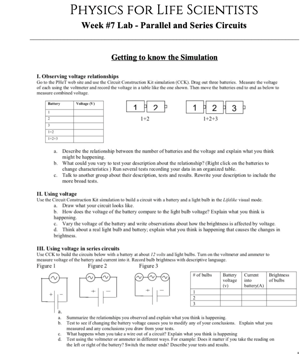
PHYSICS FOR LIFE SCIENTISTS Week #7 Lab - Parallel and Series Circuits Getting to know the Simulation I. Observing voltage relationships Go to the PHeT


Step by Step Solution
There are 3 Steps involved in it
Step: 1

Get Instant Access to Expert-Tailored Solutions
See step-by-step solutions with expert insights and AI powered tools for academic success
Step: 2

Step: 3
Ace Your Homework with AI
Get the answers you need in no time with our AI-driven, step-by-step assistance
Get Started
Physics For Scientists And Engineers With Modern Physics
Authors: Raymond A. Serway, John W. Jewett
9th Edition
1133954057, 978-1133954057