Answered step by step
Verified Expert Solution
Question
1 Approved Answer
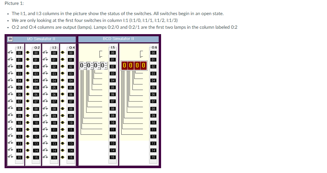
Picture 1: The I:1, and I:3 columns in the picture show the status of the switches. All switches begin in an open state. .


Picture 1: The I:1, and I:3 columns in the picture show the status of the switches. All switches begin in an open state. . We are only looking at the frst four switches in column I:1 )I:1/0, I:1/1, I:1/2, I:1/3) 0:2 and 0:4 columns are output (lamps). Lamps 0:2/0 and 0:2/1 are the first two lamps in the column labeled 0:2 BCD Simulator II -1:1 6000 . . . . . . . . . . . . . 603 01 02 60 605 60 04 08 09 10 I/O Simulator II 14 15 . 0:2 00 01 06 07 - 07 0202 0303 1:3 6. m 01 04 04 05 05 06 06 07 08 08 0909 10 10 1111 12 12 13 13 14 14 15 15 0:4 00 01 03 04 05 06 07 08 09 10 12 13 14 15 -1:5 01 0 0 0 0 03 04 05 06 07 08 09 10 11 12 13 14 15 - 0:6 00 01 000002 03 04 05 06 07 08 09 10 11 12 13 14 15 Picture 2: Ladder Logic - This picture is the ladder logic what will be loaded into the PLC. LAD 2 Relay Logic Introductory Exercise -- 3-Way Switch Control Emulation L:1/0 51/2 Switch 0 Switch 1 000 001 002 51/8 1/2 Switch 0 Switch 1 Alternative Method 51/2 41/2 Switch 2 Switch 3 1/3 11/2 Switch 2 Switch 3 Answer the following below: (Fach question is worth 3 nts) 0-210 Lamp 0 0:2/1 Lamp 1 (END>
Step by Step Solution
There are 3 Steps involved in it
Step: 1

Get Instant Access to Expert-Tailored Solutions
See step-by-step solutions with expert insights and AI powered tools for academic success
Step: 2

Step: 3

Ace Your Homework with AI
Get the answers you need in no time with our AI-driven, step-by-step assistance
Get Started


