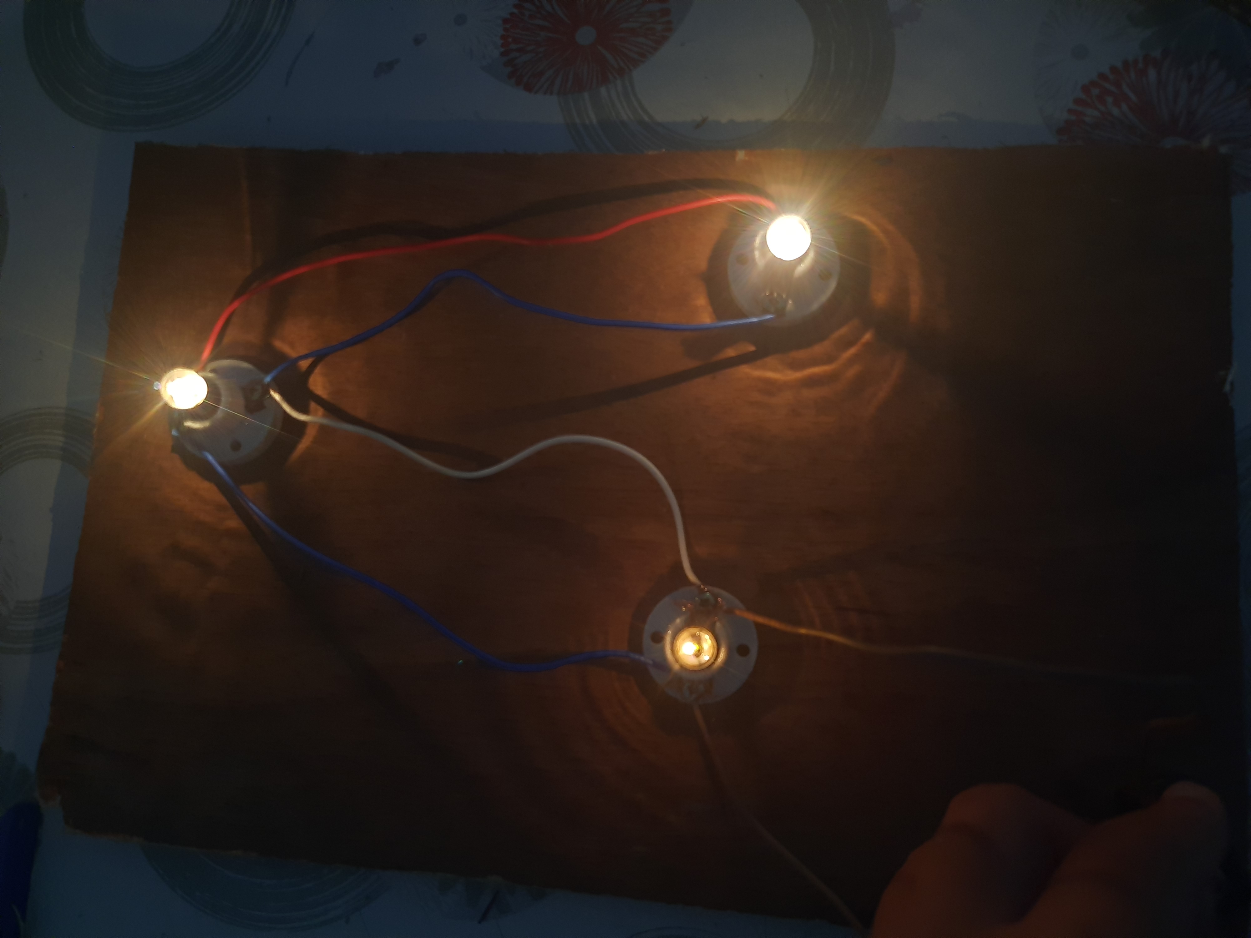
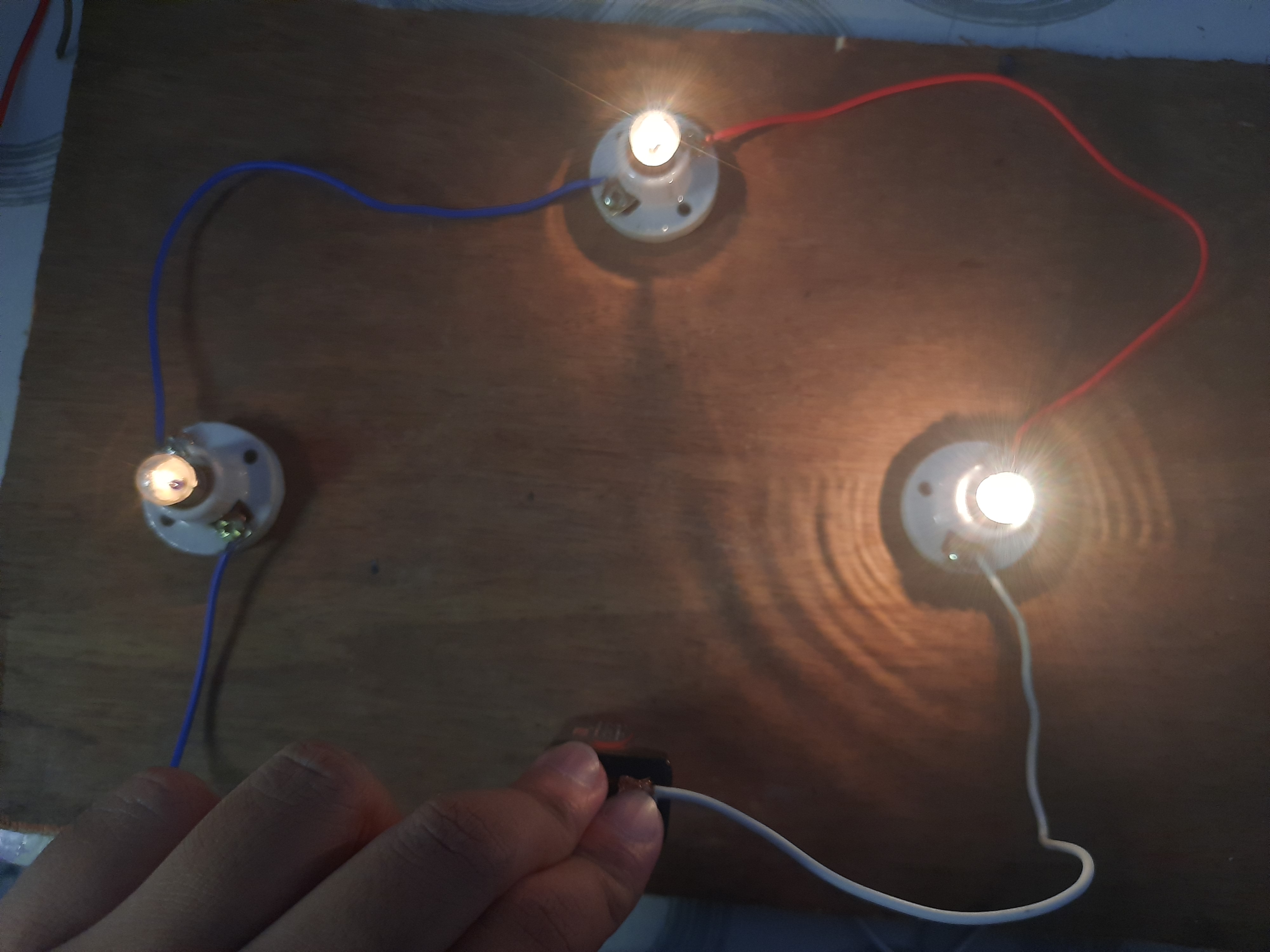
please answer all the needed data and label the V,I,R,P on the circuit board the bulbs are 2.5v the wire are 20 cm long the
please answer all the needed data and label the V,I,R,P on the circuit board
the bulbs are 2.5v
the wire are 20 cm long
the battery is 9 volts
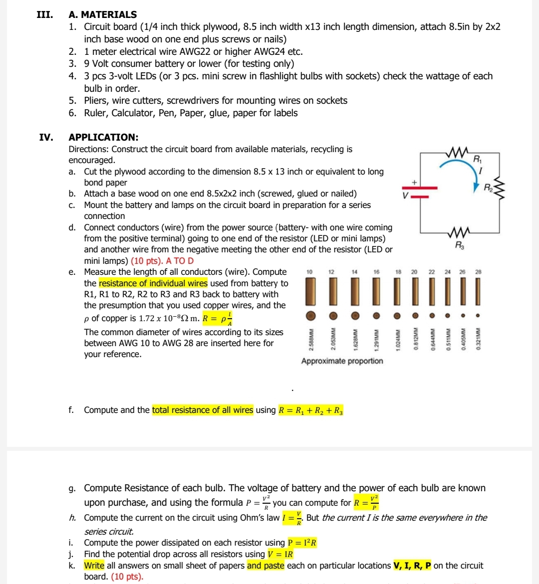
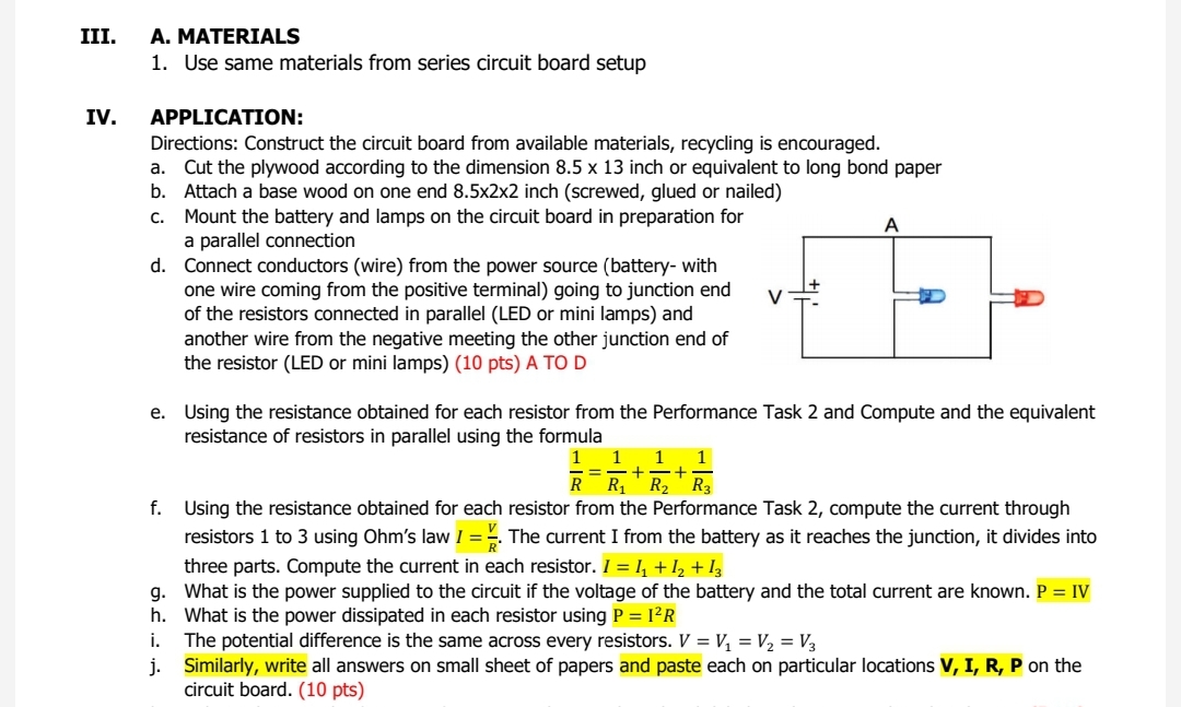
III. A. MATERIALS 1. Circuit board (1/4 inch thick plywood, 8.5 inch width x13 inch length dimension, attach 8.5in by 2x2 inch base wood on one end plus screws or nails) 2. 1 meter electrical wire AWG22 or higher AWG24 etc. 3. 9 Volt consumer battery or lower (for testing only) 4. 3 pcs 3-volt LEDs (or 3 pcs. mini screw in flashlight bulbs with sockets) check the wattage of each bulb in order. 5. Pliers, wire cutters, screwdrivers for mounting wires on sockets 6. Ruler, Calculator, Pen, Paper, glue, paper for labels IV. APPLICATION: Directions: Construct the circuit board from available materials, recycling is M encouraged. Cut the plywood according to the dimension 8.5 x 13 inch or equivalent to long bond paper Attach a base wood on one end 8.5x2x2 inch (screwed, glued or nailed) Mount the battery and lamps on the circuit board in preparation for a series connection d. Connect conductors (wire) from the power source (battery- with one wire coming from the positive terminal) going to one end of the resistor (LED or mini lamps) M and another wire from the negative meeting the other end of the resistor (LED or R3 mini lamps) (10 pts). A TO D e. Measure the length of all conductors (wire). Compute 10 22 24 26 the resistance of individual wires used from battery to R1, R1 to R2, R2 to R3 and R3 back to battery with the presumption that you used copper wires, and the p of copper is 1.72 x 10-802 m. R = p- The common diameter of wires according to its sizes 0.321MM 2.053MM 0.812MM 2.588MM 1.628MM 0.644MM 0.511MM 0.405MM between AWG 10 to AWG 28 are inserted here for 1.024MM your reference. Approximate proportion f. Compute and the total resistance of all wires using R = R, + R2 + R3 g. Compute Resistance of each bulb. The voltage of battery and the power of each bulb are known upon purchase, and using the formula P = - you can compute for R= h. Compute the current on the circuit using Ohm's law 1 = 2. But the current I is the same everywhere in the series circuit. i. Compute the power dissipated on each resistor using P = 12 R j. Find the potential drop across all resistors using V = IR K . Write all answers on small sheet of papers and paste each on particular locations V, I, R, P on the circuit board. (10 pts).III. IV. A. MATERIALS 1. Use same materials from series circuit board setup APPLICATION: Directions: Construct the circuit board from available materials, recycling is encouraged. a. b. c. G. en"??- Cut the plywood according to the dimension 8.5 x 13 inch or equivalent to long bond paper Attach a base wood on one end 8.5x2x2 inch (screwed, glued or nailed) Mount the battery and lamps on the circuit board in preparation for A a parallel connection Connect conductors (wire) from the power source (battery- with one wire coming from the positive terminal) going to junction end V + of the resistors connected in parallel (LED or mini lamps) and another wire from the negative meeting the other junction end of the resistor (LED or mini lamps) (10 pls) A TO D Using the resistance obtained for each resistor from the Performance Task 2 and Compute and the equivalent resistance of resistors in parallel using the formula 1 1 1 1 Using the resistance obtained for each resistor from the Performance Task 2, compute the current through resistors 1 to 3 using Ohm's law I = g. The currentI from the battery as it reaches the junction, it divides into three parts. Compute the current in each mister. 1 =.'1 +12 + 13 What is the power supplied to the circuit if the voltage of the battery and the total current are known. P = IV What is the power dissipated in each resistor using P = 1212 The potential difference is the same across every resistors. V = V1 = V2 = V3 Similay, write at! answers on smali sheet of papers and paste each on particular locations 1:, I, II, P on the circuit board. (10 pts}
Step by Step Solution
There are 3 Steps involved in it
Step: 1
Get Instant Access to Expert-Tailored Solutions
See step-by-step solutions with expert insights and AI powered tools for academic success
Step: 2
Step: 3
Ace Your Homework with AI
Get the answers you need in no time with our AI-driven, step-by-step assistance