Question: please answer all the questions:- A wound DC motor is connected in both a shunt and a series configuration. Assume generic resistance and inductance parameters
please answer all the questions:-
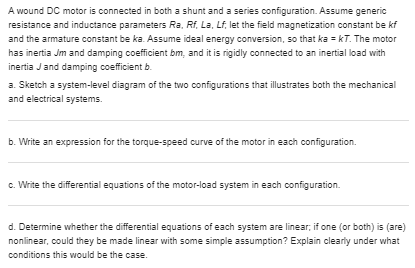
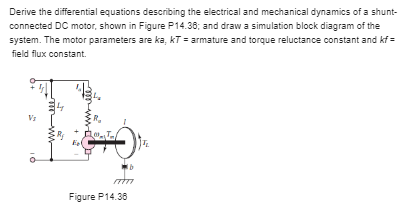
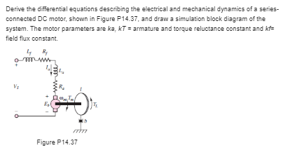


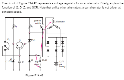


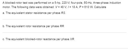
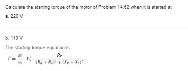
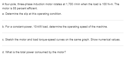
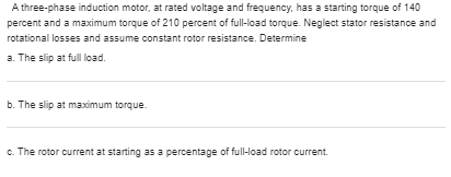
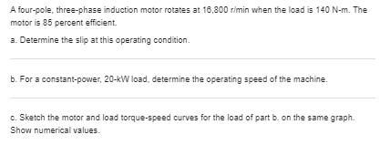
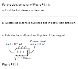
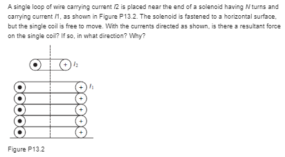
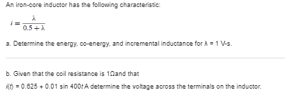
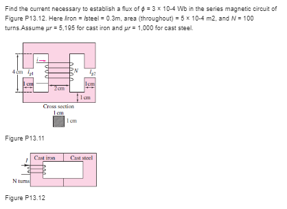
A wound DC motor is connected in both a shunt and a series configuration. Assume generic resistance and inductance parameters Ra, Rf, La, Lf, let the field magnetization constant be kf and the armature constant be ka. Assume ideal energy conversion, so that ka = KT. The motor has inertia Jm and damping coefficient bm, and it is rigidly connected to an inertial load with inertia J and damping coefficient b. a. Sketch a system-level diagram of the two configurations that illustrates both the mechanical and electrical systems. b. Write an expression for the torque-speed curve of the motor in each configuration. c. Write the differential equations of the motor-load system in each configuration. d. Determine whether the differential equations of each system are linear; if one (or both) is (are) non linear, could they be made linear with some simple assumption? Explain clearly under what conditions this would be the case.Derive the differential equations describing the electrical and mechanical dynamics of a shunt- connected DC motor, shown in Figure P14.36; and draw a simulation block diagram of the system. The motor parameters are ka, KT = armature and torque reluctance constant and of = field flux constant. R Man Figure P14.36Derive the differential equations describing the electrical and mechanical dynamics of a series- connected DC motor, shown in Figure P14.37, and draw a simulation block diagram of the system. The motor parameters are ka, KT = armature and torque reluctance constant and kf= field flux constant. O T W + + Figure P14.37Develop a Simulink simulator for the shunt-connected DC motor of Problem 14.36. Assume the following parameter values: La = 0.15 H; Lf = 0.05 H; Ra = 1.8 0; Rf = 0.2 0; ka = 0.8 V-s/rad; KT = 20 N-m/A; Af = 0.20 Wb/A; b = 0.1 N-m-s/rad; J = 1 kg-m2.Develop a Simulink simulator for the series-connected DC motor of Problem 14.37. Assume the following parameter values: [ = La + L/ = 0.2 H; R = Ra + Rf = 2 0; ka = 0.8 V-s/rad; kT= 20 N- m/A; kf = 0.20 Wb/A; b = 0.1 N-m-s/rad; J = 1 kg-m2It has been determined by test that the synchronous reactance X5 and armature resistance raof a 2,300-V. 500-VA, three-phase synchronous generator are 8.0 and 0.1 0. respectively. If the machine is operating at rated load and voltage at a power factor of 0.867 lagging. find the generated voltage per phase and the torque angle.The circuit of Figure P14.42 represents a voltage regulator for a car alternator. Briefly, explain the function of Q, D, Z, and SCR. Note that unlike other alternators, a car alternator is not driven at constant speed. Ignition Aliemajor 7SCR Slip Field battery Figure P14.42A factory load of 900 KW at 0.6 power factor lagging is to be increased by the addition of a synchronous motor that takes 450 KW. At what power factor must this motor operate, and what must be its kilovoltampere input if the overall power factor is to be 0.0 lagging?A non-salient pole, Y-connected, three-phase, two-pole synchronous generator is connected to a 400-V (line to line). 60-Hz, three-phase line. The stator impedance is 0.5 + /1.6 0 (per phase). The generator is delivering rated current (36 A) at unity power factor to the line. Determine the power angle for this load and the value of Eb for this condition. Sketch the phasor diagram, showing Eb, Is, and VS.A 1.200-V, three-phase, Y-connected synchronous motor takes 110 kW (exclusive of field winding loss) when operated under a certain load at 1,200 rimin. The back emf of the motor is 2,000 V. The synchronous reactance is 10 0 per phase, with negligible winding resistance. Find the line current and the torque developed by the motor.A six-pole induction motor for vehicle traction has a 50-KW input electric power rating and is 85 percent efficient. If the supply is 220 V at 80 Hz, compute the motor speed and torque at a slip of 0.04.A blocked-rotor test was performed on a 5-hp. 220-V, four-pole, 60-Hz, three-phase induction motor. The following data were obtained: V = 48 V. / = 18 A, P = 610 W. Calculate a. The equivalent stator resistance per phase RS. b. The equivalent rotor resistance per phase RR. c. The equivalent blocked-rotor reactance per phase XR.Calculate the starting torque of the motor of Problem 14.62 when it is started at a. 220 V b. 110 V The starting torque equation is T = (Rx + Rs) + (Xx + X5)2A four-pole, three-phase induction motor rotates at 1,700 w/min when the load is 100 N-m. The motor is 88 percent efficient. a. Determine the slip at this operating condition. b. For a constant-power, 10-KW load. determine the operating speed of the machine. c. Sketch the motor and load torque-speed curves on the same graph. Show numerical values. d. What is the total power consumed by the motor?A three-phase induction motor, at rated voltage and frequency, has a starting torque of 140 percent and a maximum torque of 210 percent of full-load torque. Neglect stator resistance and rotational losses and assume constant rotor resistance. Determine a. The slip at full load. b. The slip at maximum torque. c. The rotor current at starting as a percentage of full-load rotor current.A four-pole, three-phase induction motor rotates at 18,800 r/min when the load is 140 N-m. The motor is 85 percent efficient. a. Determine the slip at this operating condition. b. For a constant-power, 20-KW load, determine the operating speed of the machine. c. Sketch the motor and load torque-speed curves for the load of part b. on the same graph. Show numerical values.For the electromagnet of Figure P13.1: a. Find the flux density in the core b. Sketch the magnetic flux lines and indicate their direction. c. Indicate the north and south poles of the magnet. Cross-sectional 0=4 x 10 * Wb area =0.01 m Figure P13.1A single loop of wire carrying current /2 is placed near the end of a solenoid having / turns and carrying current /, as shown in Figure P13.2. The solenoid is fastened to a horizontal surface, but the single coil is free to move. With the currents directed as shown, is there a resultant force on the single coil? If so, in what direction? Why? O (+ ooooo Figure P13.2An iron-core inductor has the following characteristic: 0.5 + A a. Determine the energy, co-energy, and incremental inductance for A = 1 V-s. b. Given that the coil resistance is 10and that My = 0.625 + 0.01 sin 400fA determine the voltage across the terminals on the inductor.Find the current necessary to establish a flux of @ = 3 x 10⁻⁴ Wb in the series magnetic circuit of Figure P13.12. Here Airon = /steel = 0.3m, area (throughout) = 5 x 10⁻⁴ m2, and N = 100 turns.Assume pr = 5.195 for cast iron and ur = 1,000 for cast steel. PN I cm Icm 2 cm 1 em Cross section I em 1 em Figure P13.11 Cast iron Cast steel Figure P13.12
Step by Step Solution
There are 3 Steps involved in it

Get step-by-step solutions from verified subject matter experts


