

Answered step by step
Verified Expert Solution
Question
1 Approved Answer
&&&%%%$$$ Please answer all the questions.. Lab Outcomes: By the end of this lab, students should be able to: 1. Design the hardware interface between
&&&%%%$$$
Please answer all the questions..
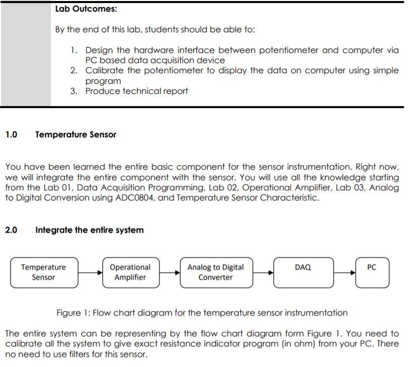
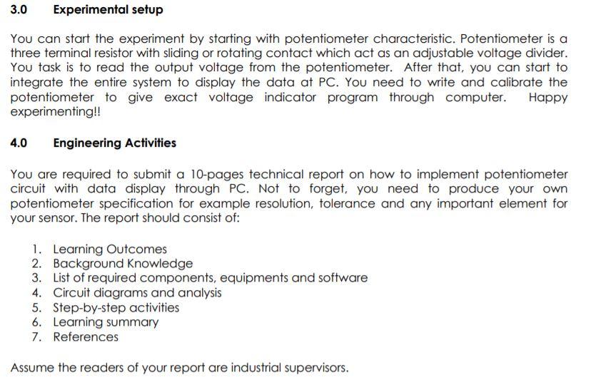
Lab Outcomes: By the end of this lab, students should be able to: 1. Design the hardware interface between potentiometer and computer via PC based data acquisition device 2. Calibrate the potentiometer to display the data on computer using simple program 3. Produce technical report 1.0 Temperature Sensor You have been learned the entire basic component for the sensor instrumentation. Right now, we will integrate the entire component with the sensor. You will use all the knowledge starting from the Lab 01, Data Acquisition Programming, Lab 02, Operational Amplifier, Lab 03, Analog to Digital Conversion using ADC0804, and Temperature Sensor Characteristic. 2.0 Integrate the entire system DAQ Temperature Sensor Operational Amplifier PC Analog to Digital Converter Figure 1: Flow chart diagram for the temperature sensor instrumentation The entire system can be representing by the flow chart diagram form Figure 1. You need to calibrate all the system to give exact resistance indicator program (in ohm) from your PC. There no need to use filters for this sensor. 3.0 Experimental setup You can start the experiment by starting with potentiometer characteristic. Potentiometer is a three terminal resistor with sliding or rotating contact which act as an adjustable voltage divider. You task is to read the output voltage from the potentiometer. After that, you can start to integrate the entire system to display the data at PC. You need to write and calibrate the potentiometer to give exact voltage indicator program through computer. Happy experimenting!! 4.0 Engineering Activities You are required to submit a 10-pages technical report on how to implement potentiometer circuit with data display through PC. Not to forget, you need to produce your own potentiometer specification for example resolution, tolerance and any important element for your sensor. The report should consist of: 1. Learning Outcomes 2. Background Knowledge 3. List of required components, equipments and software 4. Circuit diagrams and analysis 5. Step-by-step activities 6. Learning summary 7. References Assume the readers of your report are industrial supervisors. Lab Outcomes: By the end of this lab, students should be able to: 1. Design the hardware interface between potentiometer and computer via PC based data acquisition device 2. Calibrate the potentiometer to display the data on computer using simple program 3. Produce technical report 1.0 Temperature Sensor You have been learned the entire basic component for the sensor instrumentation. Right now, we will integrate the entire component with the sensor. You will use all the knowledge starting from the Lab 01, Data Acquisition Programming, Lab 02, Operational Amplifier, Lab 03, Analog to Digital Conversion using ADC0804, and Temperature Sensor Characteristic. 2.0 Integrate the entire system DAQ Temperature Sensor Operational Amplifier PC Analog to Digital Converter Figure 1: Flow chart diagram for the temperature sensor instrumentation The entire system can be representing by the flow chart diagram form Figure 1. You need to calibrate all the system to give exact resistance indicator program (in ohm) from your PC. There no need to use filters for this sensor. 3.0 Experimental setup You can start the experiment by starting with potentiometer characteristic. Potentiometer is a three terminal resistor with sliding or rotating contact which act as an adjustable voltage divider. You task is to read the output voltage from the potentiometer. After that, you can start to integrate the entire system to display the data at PC. You need to write and calibrate the potentiometer to give exact voltage indicator program through computer. Happy experimenting!! 4.0 Engineering Activities You are required to submit a 10-pages technical report on how to implement potentiometer circuit with data display through PC. Not to forget, you need to produce your own potentiometer specification for example resolution, tolerance and any important element for your sensor. The report should consist of: 1. Learning Outcomes 2. Background Knowledge 3. List of required components, equipments and software 4. Circuit diagrams and analysis 5. Step-by-step activities 6. Learning summary 7. References Assume the readers of your report are industrial supervisorsStep by Step Solution
There are 3 Steps involved in it
Step: 1

Get Instant Access to Expert-Tailored Solutions
See step-by-step solutions with expert insights and AI powered tools for academic success
Step: 2

Step: 3
Ace Your Homework with AI
Get the answers you need in no time with our AI-driven, step-by-step assistance
Get Started
Conceptual Database Design An Entity Relationship Approach
Authors: Carol Batini, Stefano Ceri, Shamkant B. Navathe
1st Edition
0805302441, 978-0805302448