

Question: Please answer both parts a and b, or don't answer this question at all. Thanks If you have answered this question before, please do not
Please answer both parts a and b, or don't answer this question at all. Thanks
If you have answered this question before, please do not answer it again. Thank you (please read)
Please draw diagrams and make sure the answer is clear. Please show steps
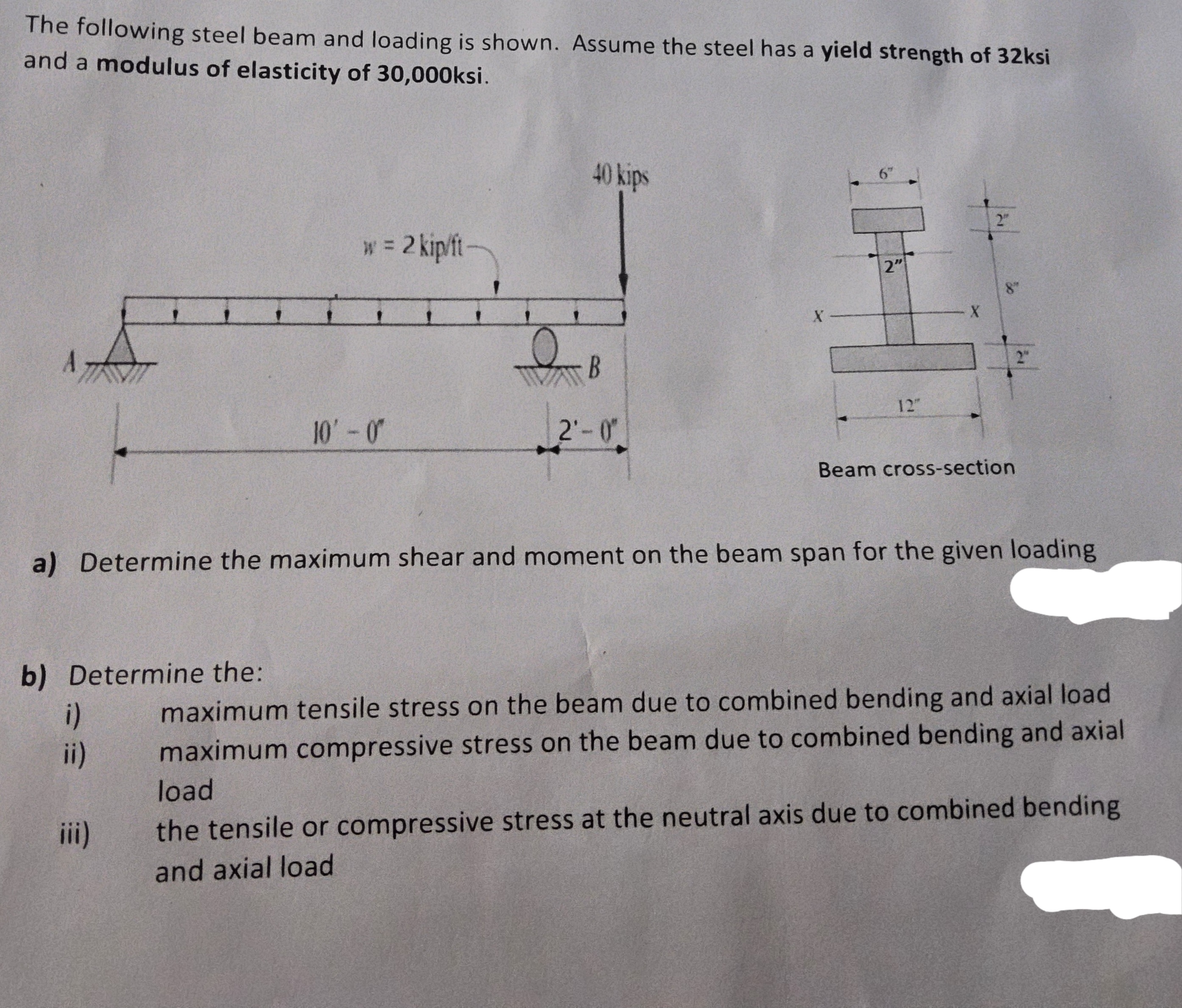
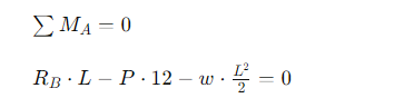
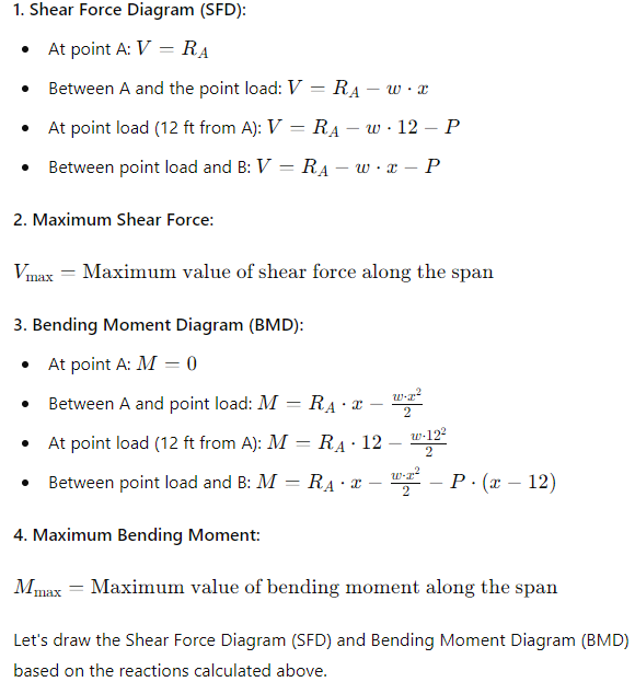
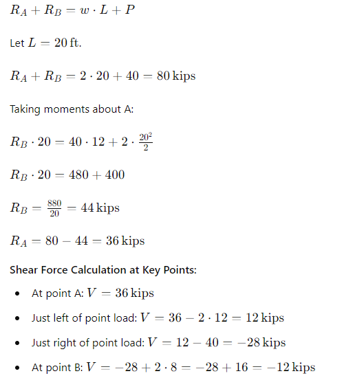
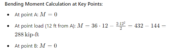
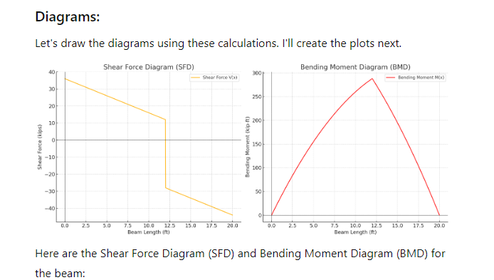
The following steel beam and loading is shown. Assume the steel has a yield strength of 32ksi and a modulus of elasticity of 30,000ksi. 40 kips 2" w = 2 kip/fi- X 2" 12" 10' - 0" 2'-0' Beam cross-section a) Determine the maximum shear and moment on the beam span for the given loading b) Determine the: i) maximum tensile stress on the beam due to combined bending and axial load ii) maximum compressive stress on the beam due to combined bending and axial load iii) the tensile or compressive stress at the neutral axis due to combined bending and axial load\f1. Shear Force Diagram (SFD): . At point A: V = RA . Between A and the point load: V - RA - w . . At point load (12 ft from A): V - RA - w . 12 - P Between point load and B: V = RA - w . x - P 2. Maximum Shear Force: Vmax = Maximum value of shear force along the span 3. Bending Moment Diagram (BMD): . At point A: M = 0 Between A and point load: M - RA . x - 2 . At point load (12 ft from A): M - RA . 12 W.122 2 . Between point load and B: M - RA . x - 2 P . (x - 12) 4. Maximum Bending Moment: Mmax - Maximum value of bending moment along the span Let's draw the Shear Force Diagram (SFD) and Bending Moment Diagram (BMD) based on the reactions calculated above.RA+RB = W . L+P Let L = 20 ft. RA+ RB = 2 . 20 + 40 - 80 kips Taking moments about A: RB . 20 - 40 . 12 + 2 . 20 2 RB . 20 = 480 + 400 RB = 880 20 - 44 kips RA = 80 - 44 - 36 kips Shear Force Calculation at Key Points: . At point A: V = 36 kips . Just left of point load: V = 36 - 2 . 12 - 12 kips . Just right of point load: V = 12 - 40 - -28 kips . At point B: V - -28 + 2 . 8 - -28 + 16 - -12 kipsBending Moment Calculation at Key Points: At point A: M = 0 At point load (12 ft from A): M - 36 . 12 - 2.12- 2 - 432 - 144 = 288 kip-ft . At point B: M = 0Diagrams: Let's draw the diagrams using these calculations. I'll create the plots next. Shear Force Diagram (SFD) Bending Moment Diagram (BMD) 40 300 Shoar Force Vix) - Banding Moment Mic) 30 250 20 10 200 150 Shear Force (kips) Bending Moment (kip. -10 100 -20 -30 50 -40 2.5 5.0 7.5 10.0 12.5 15.0 17.5 20.0 D.D 2.5 5.0 7.5 10.0 12 5 15.0 17.5 20.0 Beam Length Of) Beam Length Ift) Here are the Shear Force Diagram (SFD) and Bending Moment Diagram (BMD) for the beam
Step by Step Solution
There are 3 Steps involved in it

Get step-by-step solutions from verified subject matter experts