 Please Answer Each question, Thanks!
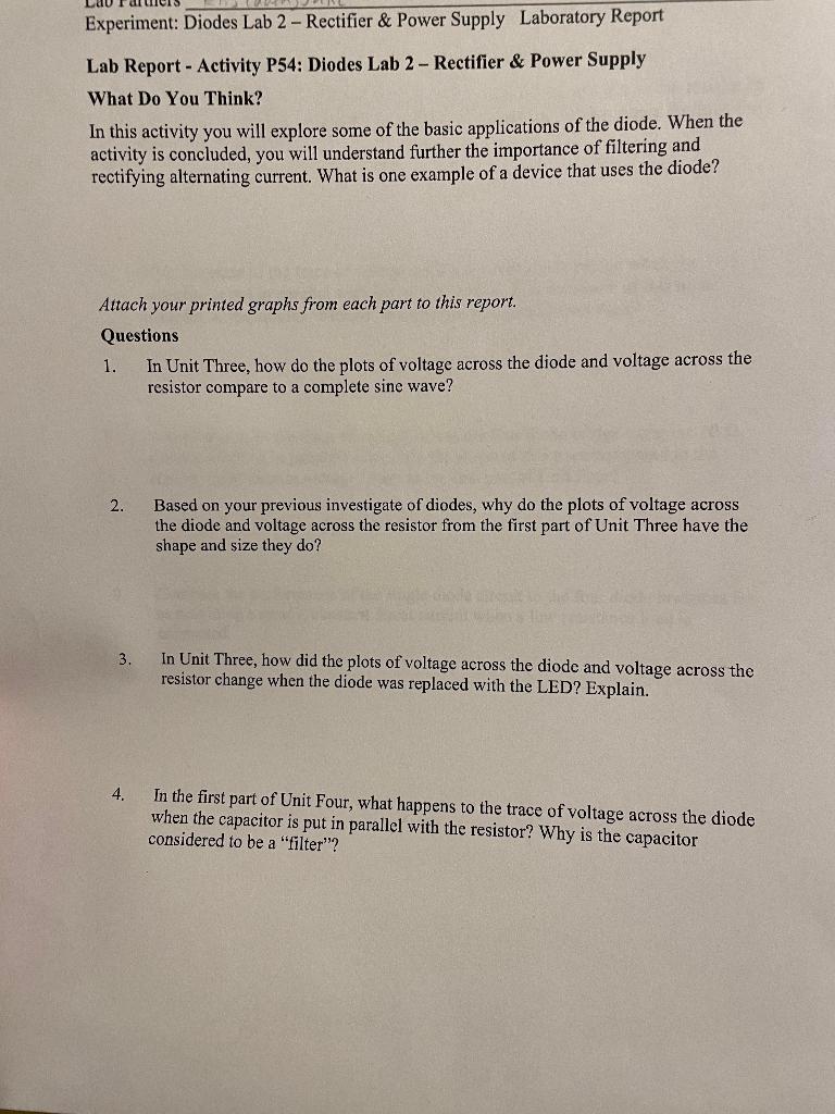
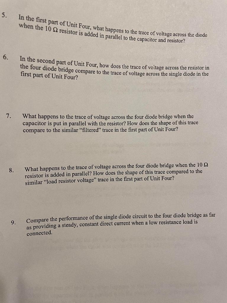
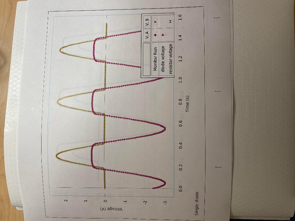
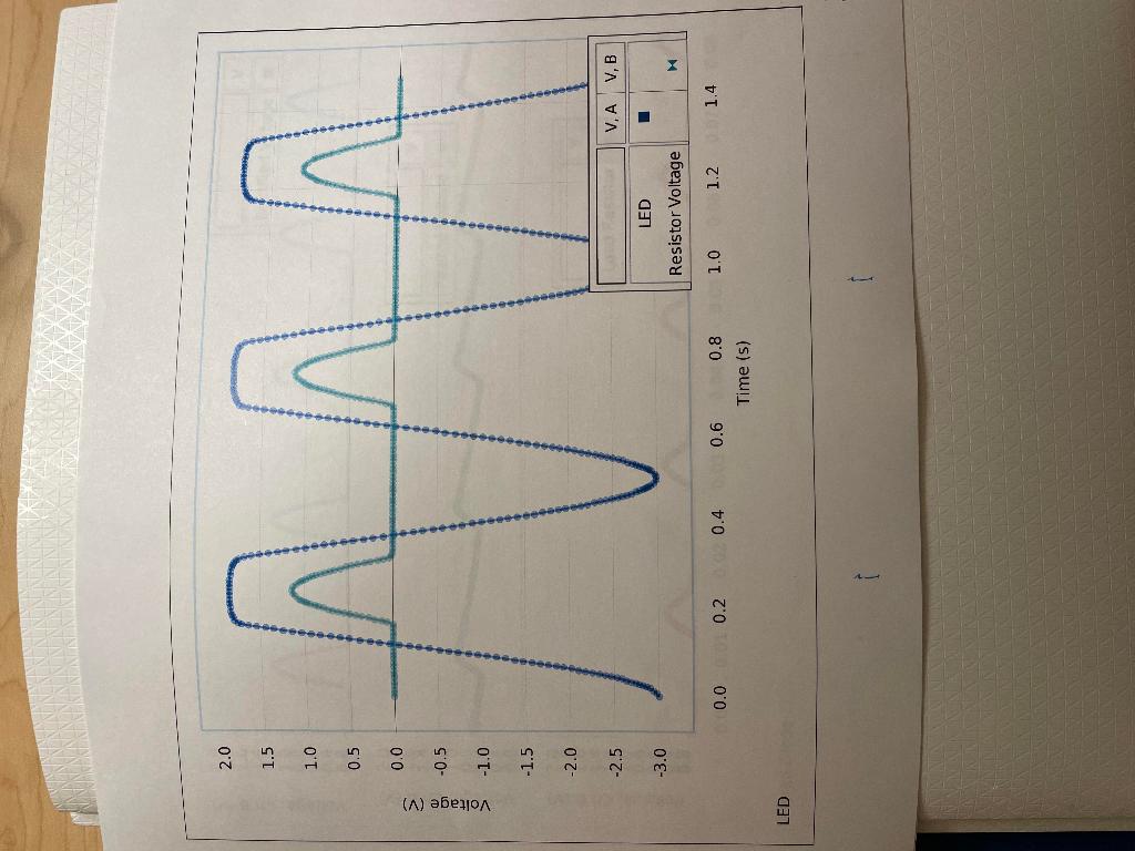
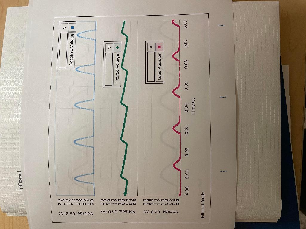
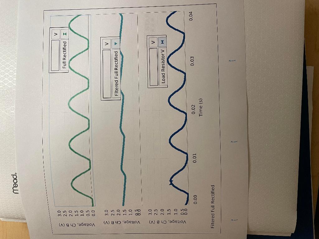
Experiment: Diodes Lab 2 - Rectifier \& Power Supply Laboratory Report Lab Report - Activity P54: Diodes Lab 2 - Rectifier \& Power Supply What Do You Think? In this activity you will explore some of the basic applications of the diode. When the activity is concluded, you will understand further the importance of filtering and rectifying alternating current. What is one example of a device that uses the diode? Attach your printed graphs from each part to this report. Questions 1. In Unit Three, how do the plots of voltage across the diode and voltage across the resistor compare to a complete sine wave? 2. Based on your previous investigate of diodes, why do the plots of voltage across the diode and voltage across the resistor from the first part of Unit Three have the shape and size they do? 3. In Unit Three, how did the plots of voltage across the diode and voltage across the resistor change when the diode was replaced with the LED? Explain. 4. In the first part of Unit Four, what happens to the trace of voltage across the diode when the capacitor is put in parallel with the resistor? Why is the capacitor considered to be a "filter"? 5. In the first part of Unit Four, what happens to the trace of yoltage across the diode when the 10 resistor is added in parallel to the capacitor and resistor? 6. In the second part of Unit Four, how does the trace of voltage across the resistor in the four diode bridge compare to the trace of voltage across the single diode in the first part of Unit Four? 7. What happens to the trace of voltage across the four diode bridge when the capacitor is put in parallel with the resistor? How does the shape of this trace compare to the similar "filtered" trace in the first part of Unit Four? 8. What happens to the trace of voltage across the four diode bridge when the 10 resistor is added in parallel? How does the shape of this trace compared to the similar "load resistor voltage" trace in the first part of Unit Four? 9. Compare the performance of the single diode circuit to the four diode bridge as far as providing a steady, constant direct current when a low resistance load is connected. monel 1.6001.20000>2.01.81.41.00.80.60.40.0 \begin{tabular}{ll} oj & 1.0 \\ & 0.8 \\ \hline & 0.6 \\ \hline & 0.4 \\ > & 0.8 \end{tabular} Time (5) Filtered Diode meado 0in0in03>3.02.52.01.51.00.50.0 m3c00t>3.02.52.01.51.01.58.0 uc3.02.52.0 \begin{tabular}{ll} i) & 1.5 \\ o) & 1.0 \\ & 1.0 \\ > & 0.5 \\ \hline & 0.0 \end{tabular} Time (s) Filtered Full Rectified Experiment: Diodes Lab 2 - Rectifier \& Power Supply Laboratory Report Lab Report - Activity P54: Diodes Lab 2 - Rectifier \& Power Supply What Do You Think? In this activity you will explore some of the basic applications of the diode. When the activity is concluded, you will understand further the importance of filtering and rectifying alternating current. What is one example of a device that uses the diode? Attach your printed graphs from each part to this report. Questions 1. In Unit Three, how do the plots of voltage across the diode and voltage across the resistor compare to a complete sine wave? 2. Based on your previous investigate of diodes, why do the plots of voltage across the diode and voltage across the resistor from the first part of Unit Three have the shape and size they do? 3. In Unit Three, how did the plots of voltage across the diode and voltage across the resistor change when the diode was replaced with the LED? Explain. 4. In the first part of Unit Four, what happens to the trace of voltage across the diode when the capacitor is put in parallel with the resistor? Why is the capacitor considered to be a "filter"? 5. In the first part of Unit Four, what happens to the trace of yoltage across the diode when the 10 resistor is added in parallel to the capacitor and resistor? 6. In the second part of Unit Four, how does the trace of voltage across the resistor in the four diode bridge compare to the trace of voltage across the single diode in the first part of Unit Four? 7. What happens to the trace of voltage across the four diode bridge when the capacitor is put in parallel with the resistor? How does the shape of this trace compare to the similar "filtered" trace in the first part of Unit Four? 8. What happens to the trace of voltage across the four diode bridge when the 10 resistor is added in parallel? How does the shape of this trace compared to the similar "load resistor voltage" trace in the first part of Unit Four? 9. Compare the performance of the single diode circuit to the four diode bridge as far as providing a steady, constant direct current when a low resistance load is connected. monel 1.6001.20000>2.01.81.41.00.80.60.40.0 \begin{tabular}{ll} oj & 1.0 \\ & 0.8 \\ \hline & 0.6 \\ \hline & 0.4 \\ > & 0.8 \end{tabular} Time (5) Filtered Diode meado 0in0in03>3.02.52.01.51.00.50.0 m3c00t>3.02.52.01.51.01.58.0 uc3.02.52.0 \begin{tabular}{ll} i) & 1.5 \\ o) & 1.0 \\ & 1.0 \\ > & 0.5 \\ \hline & 0.0 \end{tabular} Time (s) Filtered Full Rectified


 Please Answer Each question, Thanks!


