Answered step by step
Verified Expert Solution
Question
1 Approved Answer
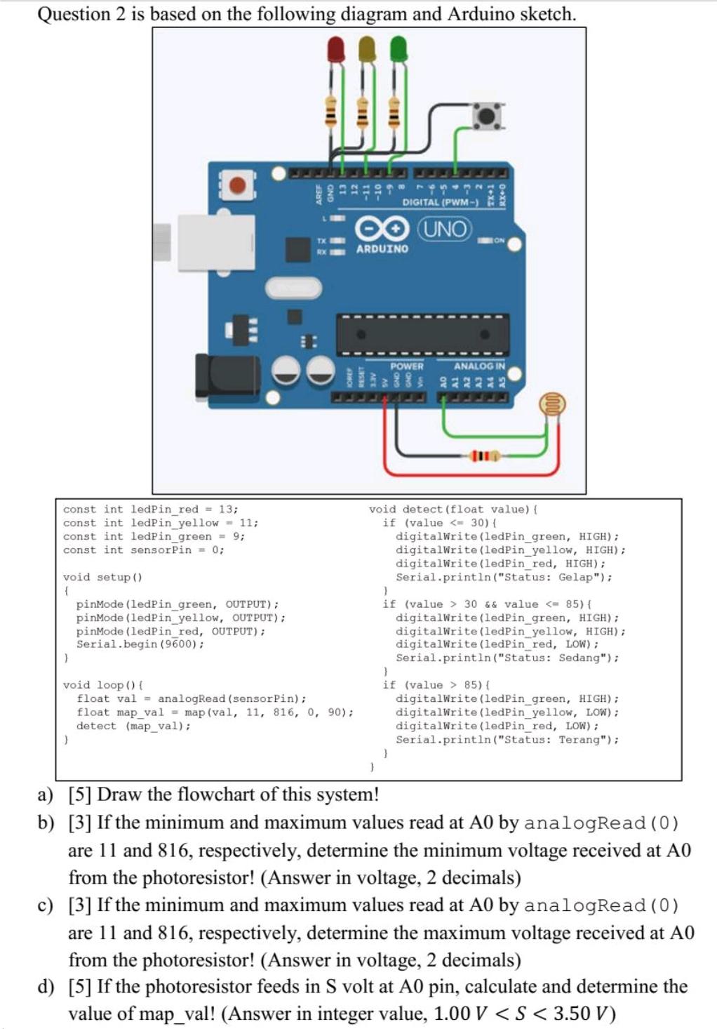
Question 2 is based on the following diagram and Arduino sketch. const int ledPin_red = 13; const int ledPin_yellow = 11; const int ledPin_green

![e) [4] If the photoresistor feeds in 3.98 V at A0 pin, determine the following outputs! Output Red LED](https://dsd5zvtm8ll6.cloudfront.net/si.experts.images/questions/2022/01/61ee91795ec08_Screenshot2022012418434311c37d74246d9c81aa0bb824b57eaf7062.jpg)
Question 2 is based on the following diagram and Arduino sketch. const int ledPin_red = 13; const int ledPin_yellow = 11; const int ledPin_green = 9; const int sensorPin = 0; void setup() { } O } pinMode(ledPin_green, OUTPUT); pinMode(ledPin_yellow, OUTPUT); pinMode(ledPin_red, OUTPUT); Serial.begin(9600); void loop() { float val analogRead (sensorPin); float map_val= map (val, 11, 816, 0, 90); detect (map_val); DIGITAL (PWM-) UNO ARDUINO POWER } RX+0 ANALOG IN 2222 void detect (float value) { if (value 30 && value 85) { digitalWrite(ledPin_green, HIGH); digitalWrite(ledPin_yellow, LOW); digitalWrite(ledPin_red, LOW); Serial.println("Status: Terang"); a) [5] Draw the flowchart of this system! b) [3] If the minimum and maximum values read at A0 by analogRead (0) are 11 and 816, respectively, determine the minimum voltage received at A0 from the photoresistor! (Answer in voltage, 2 decimals) c) [3] If the minimum and maximum values read at A0 by analogRead(0) are 11 and 816, respectively, determine the maximum voltage received at A0 from the photoresistor! (Answer in voltage, 2 decimals) d) [5] If the photoresistor feeds in S volt at A0 pin, calculate and determine the value of map_val! (Answer in integer value, 1.00 V e) [4] If the photoresistor feeds in 3.98 V at A0 pin, determine the following outputs! Output Red LED Yellow LED Green LED Output Serial Value f) [20] Modify the above Arduino sketch to incorporate the push button that is connected to pin 4! The system behaves as follows. When the button is pressed, all the 3 LEDs must be active (ON). When the button is not pressed, the system behaves as in the original sketch of problem 2. Value (Text)
Step by Step Solution
★★★★★
3.41 Rating (151 Votes )
There are 3 Steps involved in it
Step: 1
a Flowchart of the system Start Set ledPinred 13 Set ledPinyellow 11 Set ledPingreen 9 Set sensorPin ...
Get Instant Access to Expert-Tailored Solutions
See step-by-step solutions with expert insights and AI powered tools for academic success
Step: 2

Step: 3

Ace Your Homework with AI
Get the answers you need in no time with our AI-driven, step-by-step assistance
Get Started


