Question
--------------------------------------------------------------------------------------------------------------------------------------------------------------------------------------------------------------------------------------------------------- Please describe, at a system block-level, why the design of the architecture was chosen in order to achieve the design specifications and functionality that
---------------------------------------------------------------------------------------------------------------------------------------------------------------------------------------------------------------------------------------------------------
Please describe, at a system block-level, why the design of the architecture was chosen in order to achieve the design specifications and functionality that the project asks for?
---------------------------------------------------------------------------------------------------------------------------------------------------------------------------------------------------------------------------------------------------------
The design specifications for the project were:
Design a sequential system that has one synchronous input bit stream X and one output Z, with the following functionality:
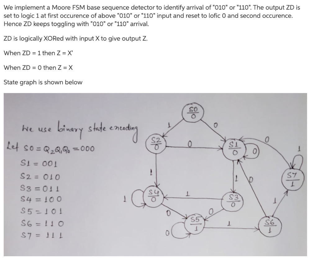
1. We look at the 010 and 110 sequences in the input stream. The system outputs the same input stream, except that one clock cycle after any of these sequences (with overlap) have been present at the input the output becomes complemented version of the input, the next sequence ( 010 or 110) to appear in the input returns the output to normal, the next sequence to appear again at the input causes the output to be again a complemented version of the input and so on and so forth.
2. The timing trace below (Moore-type) depict a possible example with various events in order to clarify the prescribed functionality.
3. Discuss any timing problem that you think your design solution may have, and give a possible alternative.
The Design Constraints of the project were:
1. Do not use more than 4 Flip-Flops of any type.
2. Minimize the use of discrete gates, multiplexers or decoders of any type.
3. The system can use any number of subsystems.
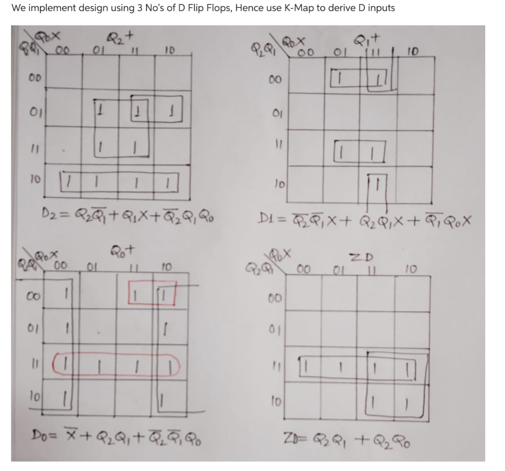
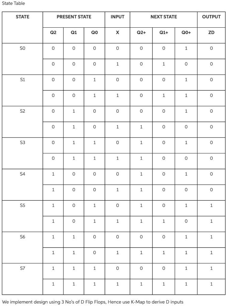
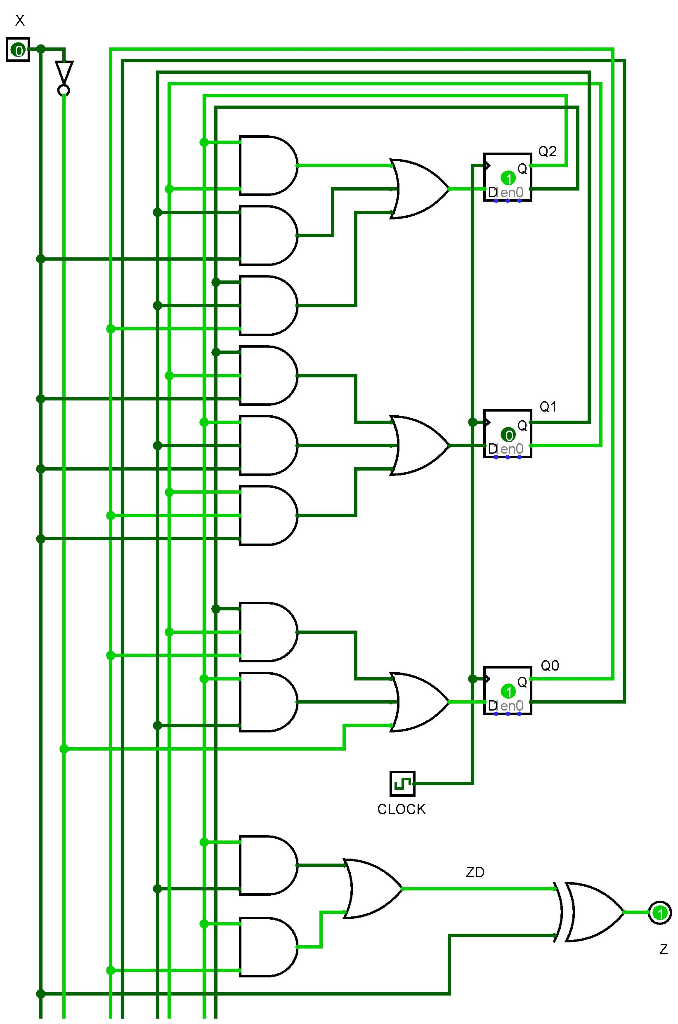
The pictures below was the final design choice for the project based on all of the rules and guidelines above.
---------------------------------------------------------------------------------------------------------------------------------------------------------------------------------------------------------------------------------------------------------
Please describe, at a system block-level, why the design of the architecture was chosen in order to achieve the design specifications and functionality that the project asks for?
---------------------------------------------------------------------------------------------------------------------------------------------------------------------------------------------------------------------------------------------------------


Step by Step Solution
There are 3 Steps involved in it
Step: 1

Get Instant Access to Expert-Tailored Solutions
See step-by-step solutions with expert insights and AI powered tools for academic success
Step: 2

Step: 3

Ace Your Homework with AI
Get the answers you need in no time with our AI-driven, step-by-step assistance
Get Started


