

Answered step by step
Verified Expert Solution
Question
1 Approved Answer
please do it 4 hour will upvote A speed reducer is to be designed for a Power Transmission System used in a small equipment. According
please do it 4 hour will upvote
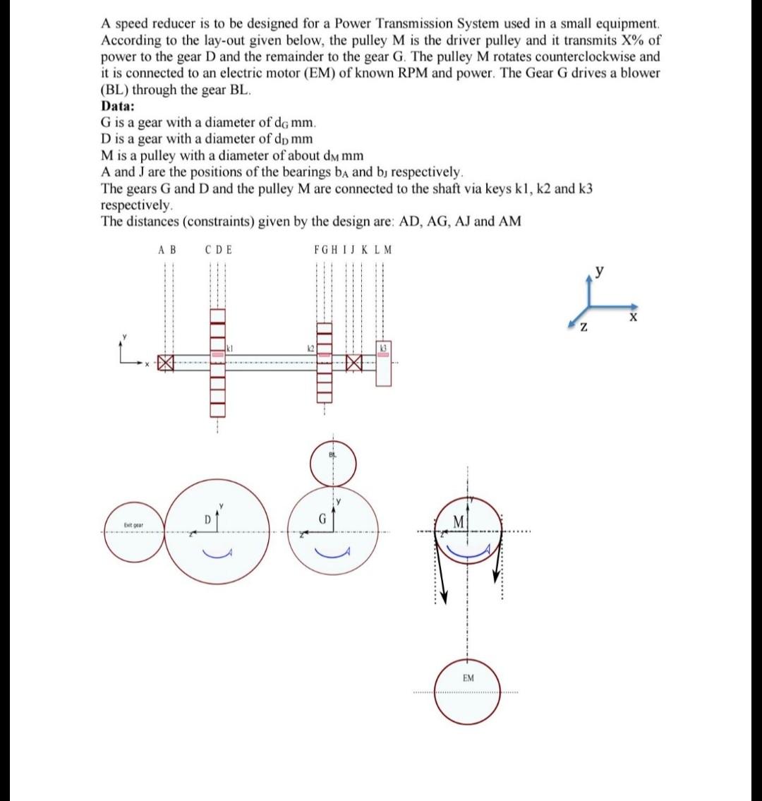
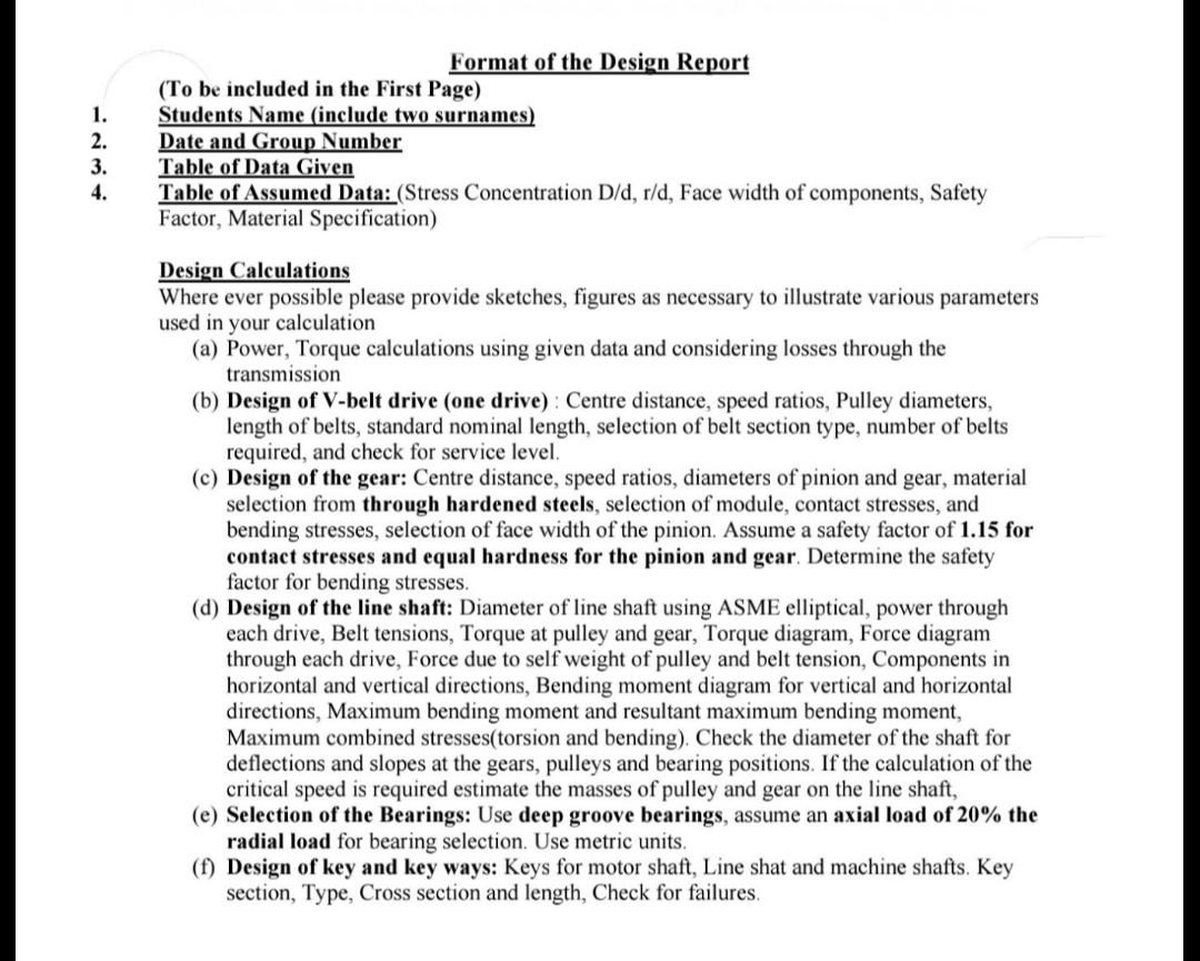
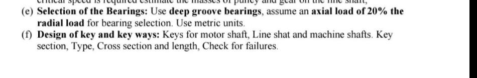
A speed reducer is to be designed for a Power Transmission System used in a small equipment. According to the lay-out given below, the pulley M is the driver pulley and it transmits X% of power to the gear D and the remainder to the gear G. The pulley M rotates counterclockwise and it is connected to an electric motor (EM) of known RPM and power. The Gear G drives a blower (BL) through the gear BL. Data: G is a gear with a diameter of dg mm. D is a gear with a diameter of dp mm M is a pulley with a diameter of about dm mm A and J are the positions of the bearings ba and b, respectively. The gears G and D and the pulley M are connected to the shaft via keys kl, k2 and k3 respectively The distances (constraints) given by the design are: AD, AG, AJ and AM A B FGHIJKLM CDE X z , ITTI Exit EM 1. 2. 3. 4. Format of the Design Report (To be included in the First Page) Students Name (include two surnames) Date and Group Number Table of Data Given Table of Assumed Data: (Stress Concentration D/d, r/d, Face width of components, Safety Factor, Material Specification) Design Calculations Where ever possible please provide sketches, figures as necessary to illustrate various parameters used in your calculation (a) Power, Torque calculations using given data and considering losses through the transmission (b) Design of V-belt drive (one drive) : Centre distance, speed ratios, Pulley diameters, length of belts, standard nominal length, selection of belt section type, number of belts required, and check for service level. (c) Design of the gear: Centre distance, speed ratios, diameters of pinion and gear, material selection from through hardened steels, selection of module, contact stresses, and bending stresses, selection of face width of the pinion. Assume a safety factor of 1.15 for contact stresses and equal hardness for the pinion and gear. Determine the safety factor for bending stresses. (d) Design of the line shaft: Diameter of line shaft using ASME elliptical, power through each drive, Belt tensions, Torque at pulley and gear, Torque diagram, Force diagram through each drive, Force due to self weight of pulley and belt tension, Components in horizontal and vertical directions, Bending moment diagram for vertical and horizontal directions, Maximum bending moment and resultant maximum bending moment, Maximum combined stresses(torsion and bending). Check the diameter of the shaft for deflections and slopes at the gears, pulleys and bearing positions. If the calculation of the critical speed is required estimate the masses of pulley and gear on the line shaft, (e) Selection of the Bearings: Use deep groove bearings, assume an axial load of 20% the radial load for bearing selection. Use metric units. (1) Design of key and key ways: Keys for motor shaft, Line shat and machine shafts, Key section, Type, Cross section and length, Check for failures, (e) Selection of the Bearings: Use deep groove bearings, assume an axial load of 20% the radial load for bearing selection. Use metric units. (f) Design of key and key ways: Keys for motor shaft, Line shat and machine shafts. Key section, Type, Cross section and length, Check for failures. A speed reducer is to be designed for a Power Transmission System used in a small equipment. According to the lay-out given below, the pulley M is the driver pulley and it transmits X% of power to the gear D and the remainder to the gear G. The pulley M rotates counterclockwise and it is connected to an electric motor (EM) of known RPM and power. The Gear G drives a blower (BL) through the gear BL. Data: G is a gear with a diameter of dg mm. D is a gear with a diameter of dp mm M is a pulley with a diameter of about dm mm A and J are the positions of the bearings ba and b, respectively. The gears G and D and the pulley M are connected to the shaft via keys kl, k2 and k3 respectively The distances (constraints) given by the design are: AD, AG, AJ and AM A B FGHIJKLM CDE X z , ITTI Exit EM 1. 2. 3. 4. Format of the Design Report (To be included in the First Page) Students Name (include two surnames) Date and Group Number Table of Data Given Table of Assumed Data: (Stress Concentration D/d, r/d, Face width of components, Safety Factor, Material Specification) Design Calculations Where ever possible please provide sketches, figures as necessary to illustrate various parameters used in your calculation (a) Power, Torque calculations using given data and considering losses through the transmission (b) Design of V-belt drive (one drive) : Centre distance, speed ratios, Pulley diameters, length of belts, standard nominal length, selection of belt section type, number of belts required, and check for service level. (c) Design of the gear: Centre distance, speed ratios, diameters of pinion and gear, material selection from through hardened steels, selection of module, contact stresses, and bending stresses, selection of face width of the pinion. Assume a safety factor of 1.15 for contact stresses and equal hardness for the pinion and gear. Determine the safety factor for bending stresses. (d) Design of the line shaft: Diameter of line shaft using ASME elliptical, power through each drive, Belt tensions, Torque at pulley and gear, Torque diagram, Force diagram through each drive, Force due to self weight of pulley and belt tension, Components in horizontal and vertical directions, Bending moment diagram for vertical and horizontal directions, Maximum bending moment and resultant maximum bending moment, Maximum combined stresses(torsion and bending). Check the diameter of the shaft for deflections and slopes at the gears, pulleys and bearing positions. If the calculation of the critical speed is required estimate the masses of pulley and gear on the line shaft, (e) Selection of the Bearings: Use deep groove bearings, assume an axial load of 20% the radial load for bearing selection. Use metric units. (1) Design of key and key ways: Keys for motor shaft, Line shat and machine shafts, Key section, Type, Cross section and length, Check for failures, (e) Selection of the Bearings: Use deep groove bearings, assume an axial load of 20% the radial load for bearing selection. Use metric units. (f) Design of key and key ways: Keys for motor shaft, Line shat and machine shafts. Key section, Type, Cross section and length, Check for failuresStep by Step Solution
There are 3 Steps involved in it
Step: 1

Get Instant Access to Expert-Tailored Solutions
See step-by-step solutions with expert insights and AI powered tools for academic success
Step: 2

Step: 3
Ace Your Homework with AI
Get the answers you need in no time with our AI-driven, step-by-step assistance
Get Started
Forensic And Investigative Accounting
Authors: D. Larry Crumbley
3rd Edition
0808017233, 9780808017233