

Answered step by step
Verified Expert Solution
Question
1 Approved Answer
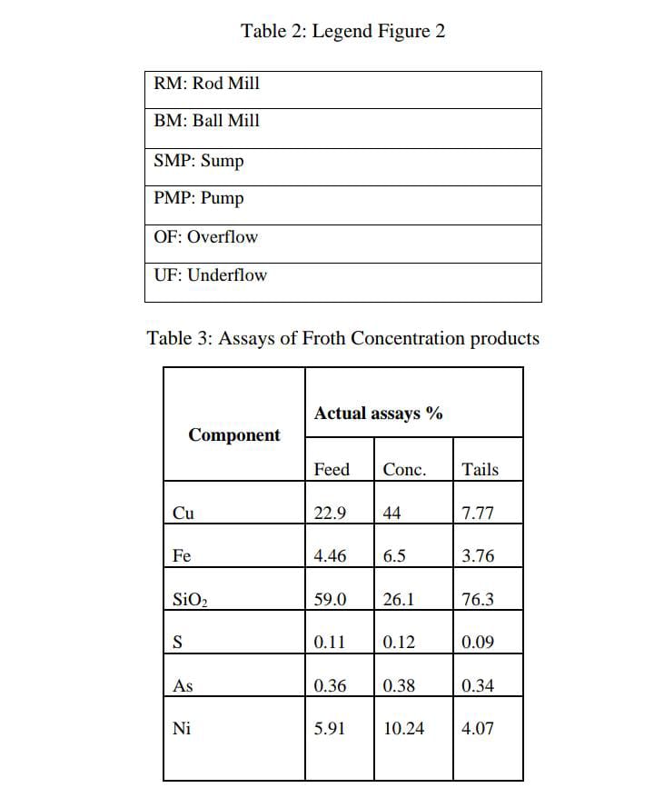
please don't explain the scenario help me with calculations for question 2 DESCRIPTION OF THE PALABORA COVENTIONAL MILLING CIRCUIT The Figure 2 represents a conventional
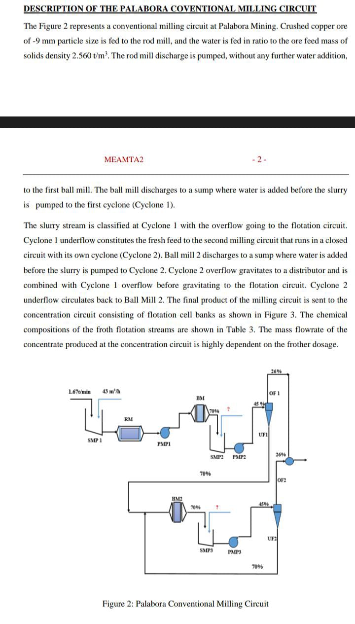
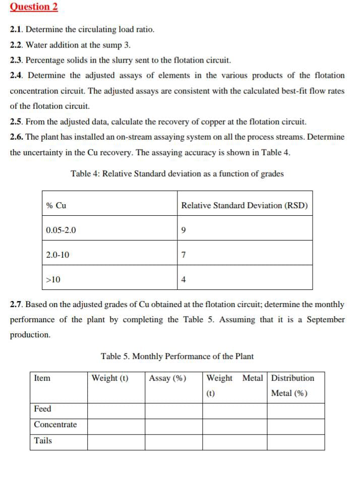 please don't explain the scenario help me with calculations for question 2
Step by Step Solution
There are 3 Steps involved in it
Step: 1

Get Instant Access to Expert-Tailored Solutions
See step-by-step solutions with expert insights and AI powered tools for academic success
Step: 2

Step: 3
Ace Your Homework with AI
Get the answers you need in no time with our AI-driven, step-by-step assistance
Get Started
Mass And Heat Transfer Analysis Of Mass Contactors And Heat Exchangers
Authors: T. W. Fraser Russell, Anne Skaja Robinson, Norman J. Wagner
1st Edition
0521886708, 9780521886703