Question: Please help me answer Part 1 and Part 3 - Current Loop SF42 ( length 8.4 cm ) Experiment 1 - Part 1 in Answer
Please help me answer Part 1 and Part 3
- Current Loop SF42 ( length 8.4 cm )
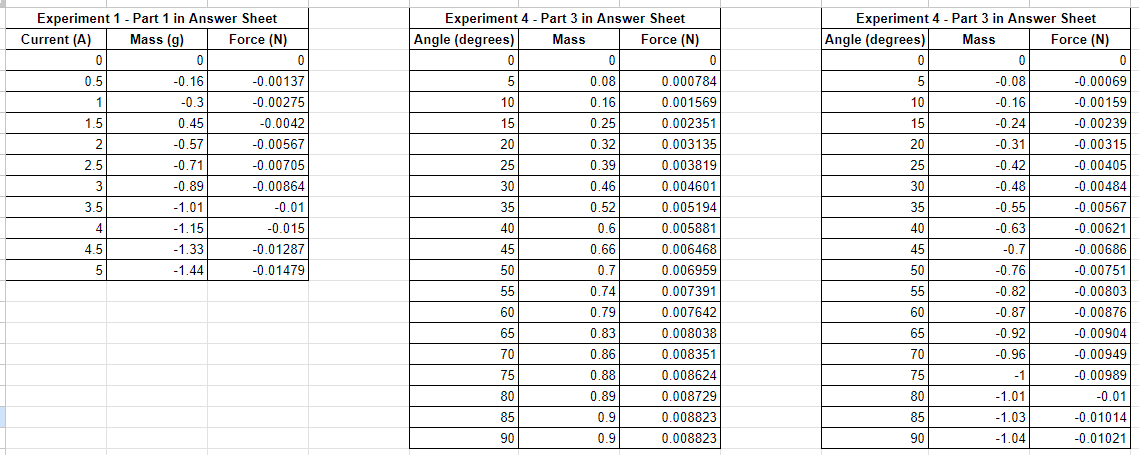
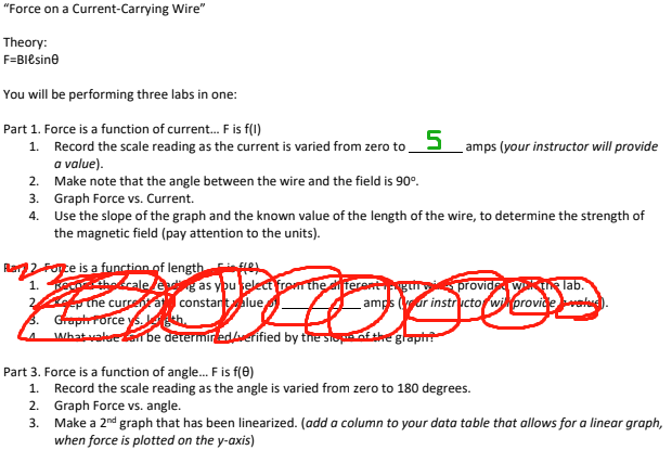
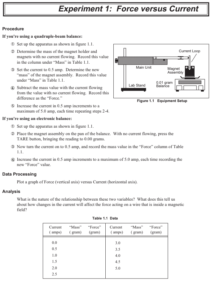
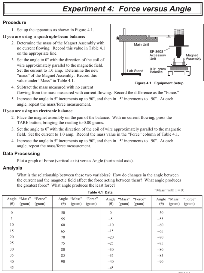
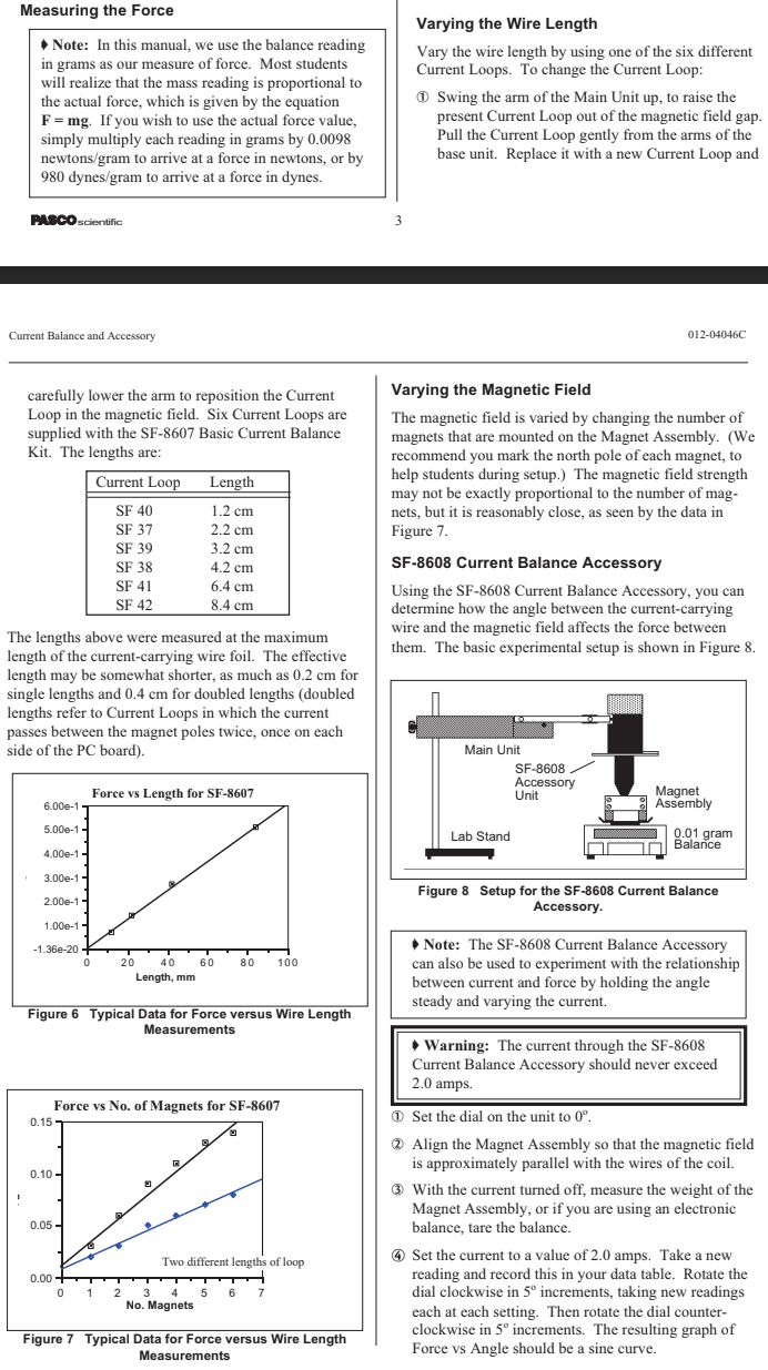
Experiment 1 - Part 1 in Answer Sheet Experiment 4 - Part 3 in Answer Sheet Experiment 4 - Part 3 in Answer Sheet Current (A) Mass (g) Force (N) Angle (degrees) Mass Force (N) Angle (degrees) Mass Force (N) 0 0 C 0 0 0 0 0.5 0. 16 0.00137 5 0.08 0.000784 5 -0.08 0.00069 -0.3 0.00275 10 0.16 0.001569 10 0.16 0.00159 1.5 0.45 0.0042 15 0.25 0.002351 15 -0.24 -0.00239 0.57 0.00567 20 0.32 0.003135 20 -0.31 -0.00315 2.5 0.71 -0.00705 25 0.39 0.003819 25 -0.42 -0.00405 0.89 -0.00864 30 0.46 0.004601 30 0.48 0.00484 3.5 1.01 0.01 35 0.52 0.005194 35 0.55 -0.00567 -1.15 -0.015 40 0.6 0.005881 40 -0.63 0.00621 4.5 -1.33 -0.01287 45 0.66 0.006468 45 -0.7 -0.00686 -1.44 -0.01479 50 0.7 0.006959 50 0.76 0.00751 55 0.74 0.007391 55 -0.82 -0.00803 60 0.79 0.007642 60 -0.87 -0.00876 65 0.83 0.008038 65 -0.92 -0.00904 70 0.86 0.008351 70 -0.96 0.00949 75 0.88 0.008624 75 -0.00989 80 0.89 0.008729 80 -1.01 -0.01 85 0.9 0.008823 85 -1.03 -0.01014 90 0.9 0.008823 90 1.04 0.01021"Force on a Current-Carrying Wire" Theory: F=Blesine You will be performing three labs in one: Part 1. Force is a function of current... F is f(1) 1. Record the scale reading as the current is varied from zero to 5 amps (your instructor will provide a value). 2. Make note that the angle between the wire and the field is 90. 3. Graph Force vs. Current. 4. Use the slope of the graph and the known value of the length of the wire, to determine the strength of the magnetic field (pay attention to the units). 1. What sale Part 3. Force is a function of angle.. F is f(0) 1. Record the scale reading as the angle is varied from zero to 180 degrees. 2. Graph Force vs. angle. 3. Make a 2nd graph that has been linearized. (add a column to your data table that allows for a linear graph, when force is plotted on the y-axis)Experiment 1: Force versus Current Procedure If you're using a quadruple-beam balance: D Set up the apparatus as shown in figure 1.1. 2 Determine the mass of the magnet holder and Current Loop magnets with no current flowing. Record this value in the column under "Mass" in Table 1.1. 3 Set the current to 0.5 amp. Determine the new Main Unit Magnet "mass" of the magnet assembly. Record this value Assembly under "Mass" in Table 1.1. 0.01 gram 4 Subtract the mass value with the current flowing Lab Stand Balance from the value with no current flowing. Record this difference as the "Force." Figure 1.1 Equipment Setup 5 Increase the current in 0.5 amp increments to a maximum of 5.0 amp, each time repeating steps 2-4. If you're using an electronic balance: D Set up the apparatus as shown in figure 1.1. 2 Place the magnet assembly on the pan of the balance. With no current flowing, press the TARE button, bringing the reading to 0.00 grams. 3 Now turn the current on to 0.5 amp, and record the mass value in the "Force" column of Table 1.1. 4 Increase the current in 0.5 amp increments to a maximum of 5.0 amp, each time recording the new "Force" value. Data Processing Plot a graph of Force (vertical axis) versus Current (horizontal axis). Analysis What is the nature of the relationship between these two variables? What does this tell us about how changes in the current will affect the force acting on a wire that is inside a magnetic field? Table 1.1 Data Current "Mass" "Force" Current "Mass" "Force" (amps) (gram) gram (amps (gram) (gram) 0.0 3.0 0.5 3.5 1.0 4.0 1.5 4.5 2.0 5.0 2.5Experiment 4: Force versus Angle Procedure 1. Set up the apparatus as shown in Figure 4.1. If you are using a quadruple-beam balance: 2. Determine the mass of the Magnet Assembly with Main Unit no current flowing. Record this value in Table 4.1 on the appropriate line. SF-8608 Accessory Magnet 3. Set the angle to 0" with the direction of the coil of Unit 9 Assembly wire approximately parallel to the magnetic field. Set the current to 1.0 amp. Determine the new Lab Stand 0.01 gram Balance "mass" of the Magnet Assembly. Record this value under "Mass" in Table 4.1. Figure 4.1 Equipment Setup 4. Subtract the mass measured with no current flowing from the mass measured with current flowing. Record the difference as the "Force." 5. Increase the angle in 5" increments up to 90", and then in -5" increments to -90". At each angle, repeat the mass/force measurement. If you are using an electronic balance: 2. Place the magnet assembly on the pan of the balance. With no current flowing, press the TARE button, bringing the reading to 0.00 grams. 3. Set the angle to 0" with the direction of the coil of wire approximately parallel to the magnetic field. Set the current to 1.0 amp. Record the mass value in the "Force" column of Table 4.1. 4. Increase the angle in 5" increments up to 90", and then in -5" increments to -90". At each angle, repeat the mass/force measurement. Data Processing Plot a graph of Force (vertical axis) versus Angle (horizontal axis). Analysis What is the relationship between these two variables? How do changes in the angle between the current and the magnetic field affect the force acting between them? What angle produces the greatest force? What angle produces the least force? Table 4.1 Data "Mass" with I = 0: Angle "Mass" "Force" Angle "Mass" "Force" Angle "Mass" "Force" Angle "Mass" "Force" (0) (gram) (gram) (0) (gram) (gram) (0) (gram) (gram) (0) (gram) (gram) 50 -50 u e 55 -5 -55 10 60 -10 -60 15 65 -15 -65 20 70 -20 -70 25 75 -25 -75 30 80 -30 -80 85 -35 -85 40 90 -40 -90Measuring the Force Varying the Wire Length * Note: In this manual, we use the balance reading Vary the wire length by using one of the six different in grams as our measure of force. Most students Current Loops. To change the Current Loop: will realize that the mass reading is proportional to the actual force, which is given by the equation D Swing the arm of the Main Unit up, to raise the F = mg. If you wish to use the actual force value, present Current Loop out of the magnetic field gap simply multiply each reading in grams by 0.0098 Pull the Current Loop gently from the arms of the newtons/gram to arrive at a force in newtons, or by base unit. Replace it with a new Current Loop and 980 dynes/gram to arrive at a force in dynes. PASCO scientific Current Balance and Accessory 012-04046C carefully lower the arm to reposition the Current Varying the Magnetic Field Loop in the magnetic field. Six Current Loops are The magnetic field is varied by changing the number of supplied with the SF-8607 Basic Current Balance magnets that are mounted on the Magnet Assembly. (We Kit. The lengths are: recommend you mark the north pole of each magnet, to Current Loop Length help students during setup.) The magnetic field strength may not be exactly proportional to the number of mag- SF 40 1.2 cm nets, but it is reasonably close, as seen by the data in SF 37 2.2 cm Figure 7. SF 39 3.2 cm SF 38 4.2 cm SF-8608 Current Balance Accessory SF 41 6.4 cm Using the SF-8608 Current Balance Accessory, you can SF 42 8.4 cm determine how the angle between the current-carrying The lengths above were measured at the maximum wire and the magnetic field affects the force between length of the current-carrying wire foil. The effective them. The basic experimental setup is shown in Figure 8. length may be somewhat shorter, as much as 0.2 cm for single lengths and 0.4 cm for doubled lengths (doubled lengths refer to Current Loops in which the current passes between the magnet poles twice, once on each side of the PC board). Main Unit SF-8608 Accessory Force vs Length for SF-8607 Unit Magnet 6.00e-1 Assembly 5.00e-1- Lab Stand 0.01 gram Balance 4.00e-1 - 3.00e-1- Figure 8 Setup for the SF-8608 Current Balance 2.00e-1 Accessory. 1.00e-1- -1.36e-20 + Note: The SF-8608 Current Balance Accessory 0 20 40 60 80 100 can also be used to experiment with the relationship Length, mm between current and force by holding the angle steady and varying the current. Figure 6 Typical Data for Force versus Wire Length Measurements * Warning: The current through the SF-8608 Current Balance Accessory should never exceed 2.0 amps. Force vs No. of Magnets for SF-8607 0.15 D Set the dial on the unit to 0". 2 Align the Magnet Assembly so that the magnetic field is approximately parallel with the wires of the coil. 0.10 - 3 With the current turned off, measure the weight of the Magnet Assembly, or if you are using an electronic 0.05 . balance, tare the balance. Two different lengths of loop 4 Set the current to a value of 2.0 amps. Take a new 0.00 - reading and record this in your data table. Rotate the 2 3 4 5 dial clockwise in 5" increments, taking new readings No. Magnets each at each setting. Then rotate the dial counter- Figure 7 Typical Data for Force versus Wire Length clockwise in 5" increments. The resulting graph of Measurements Force vs Angle should be a sine curve
Step by Step Solution
There are 3 Steps involved in it

Get step-by-step solutions from verified subject matter experts


