Answered step by step
Verified Expert Solution
Question
1 Approved Answer
please help me solve this question 1. Two liquid streams, stream 1 and stream 2 , having flow rates of q1 and q2L/min, and conc.


please help me solve this question
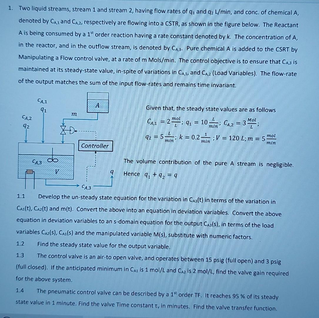
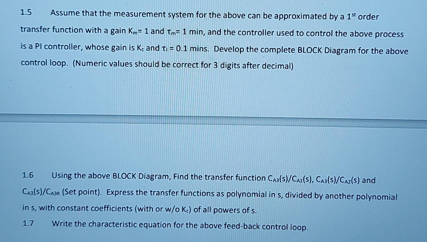
1. Two liquid streams, stream 1 and stream 2 , having flow rates of q1 and q2L/min, and conc. of chemical A, denoted by CA,1 and CA,2, respectively are flowing into a CSTR, as shown in the figure below. The Reactant A is being consumed by a 1st order reaction having a rate constant denoted by k. The concentration of A, in the reactor, and in the outflow stream, is denoted by CA,B. Pure chemical A is added to the CSRT by Manipulating a Flow control valve, at a rate of m Mols /min. The control objective is to ensure that CA3 is maintained at its steady-state value, in-spite of variations in CA,1, and CA,2 (Load Variables). The flow-rate of the output matches the sum of the input flow-rates and remains time invariant. Given that, the steady state values are as follows CA,1=2Lmol;q1=10minL;CA,2=3LMol;q2=5minL;k=0.2min1;V=120L;m=5minmol The volume contribution of the pure A stream is negligible. Hence q1+q2=q 1.1 Develop the un-steady state equation for the variation in CA3(t) in terms of the variation in CA1(t),CA2(t) and m(t). Convert the above into an equation in deviation variables. Convert the above equation in deviation variables to an s-domain equation for the output CA3(s), in terms of the load variables CA2(s),CA1(s) and the manipulated variable M(s), substitute with numeric factors. 1.2 Find the steady state value for the output variable. 1.3 The control valve is an air-to open valve, and operates between 15 psig (full open) and 3 psig (full closed). If the anticipated minimum in CA1 is 1mol/L and CA2 is 2mol/L, find the valve gain required for the above system. 1.4 The pneumatic control valve can be described by a 1st order TF. It reaches 95% of its steady state value in 1 minute. Find the valve Time constant v in minutes. Find the valve transfer function. 1.5 Assume that the measurement system for the above can be approximated by a 1st order transfer function with a gain Km=1 and m=1min, and the controller used to control the above process is a PI controller, whose gain is Kc and 1=0.1 mins. Develop the complete BLOCK Diagram for the above control loop. (Numeric values should be correct for 3 digits after decimal) 1.6 Using the above BLOCK Diagram, Find the transfer function CA3(s)/CA1(s),CA3(s)/CA2(s) and CAB(s)/CA3B (Set point). Express the transfer functions as polynomial in s, divided by another polynomial in s, with constant coefficients (with or w/oKc ) of all powers of s. 1.7 Write the characteristic equation for the above feed-back control loop. 1. Two liquid streams, stream 1 and stream 2 , having flow rates of q1 and q2L/min, and conc. of chemical A, denoted by CA,1 and CA,2, respectively are flowing into a CSTR, as shown in the figure below. The Reactant A is being consumed by a 1st order reaction having a rate constant denoted by k. The concentration of A, in the reactor, and in the outflow stream, is denoted by CA,B. Pure chemical A is added to the CSRT by Manipulating a Flow control valve, at a rate of m Mols /min. The control objective is to ensure that CA3 is maintained at its steady-state value, in-spite of variations in CA,1, and CA,2 (Load Variables). The flow-rate of the output matches the sum of the input flow-rates and remains time invariant. Given that, the steady state values are as follows CA,1=2Lmol;q1=10minL;CA,2=3LMol;q2=5minL;k=0.2min1;V=120L;m=5minmol The volume contribution of the pure A stream is negligible. Hence q1+q2=q 1.1 Develop the un-steady state equation for the variation in CA3(t) in terms of the variation in CA1(t),CA2(t) and m(t). Convert the above into an equation in deviation variables. Convert the above equation in deviation variables to an s-domain equation for the output CA3(s), in terms of the load variables CA2(s),CA1(s) and the manipulated variable M(s), substitute with numeric factors. 1.2 Find the steady state value for the output variable. 1.3 The control valve is an air-to open valve, and operates between 15 psig (full open) and 3 psig (full closed). If the anticipated minimum in CA1 is 1mol/L and CA2 is 2mol/L, find the valve gain required for the above system. 1.4 The pneumatic control valve can be described by a 1st order TF. It reaches 95% of its steady state value in 1 minute. Find the valve Time constant v in minutes. Find the valve transfer function. 1.5 Assume that the measurement system for the above can be approximated by a 1st order transfer function with a gain Km=1 and m=1min, and the controller used to control the above process is a PI controller, whose gain is Kc and 1=0.1 mins. Develop the complete BLOCK Diagram for the above control loop. (Numeric values should be correct for 3 digits after decimal) 1.6 Using the above BLOCK Diagram, Find the transfer function CA3(s)/CA1(s),CA3(s)/CA2(s) and CAB(s)/CA3B (Set point). Express the transfer functions as polynomial in s, divided by another polynomial in s, with constant coefficients (with or w/oKc ) of all powers of s. 1.7 Write the characteristic equation for the above feed-back control loopStep by Step Solution
There are 3 Steps involved in it
Step: 1

Get Instant Access to Expert-Tailored Solutions
See step-by-step solutions with expert insights and AI powered tools for academic success
Step: 2

Step: 3

Ace Your Homework with AI
Get the answers you need in no time with our AI-driven, step-by-step assistance
Get Started


