Answered step by step
Verified Expert Solution
Question
1 Approved Answer
. Please help me with this lab, much thanks. Because I need to do the entire lab in LTspice, if possible, please also include screenshot


 .
.
Please help me with this lab, much thanks.
Because I need to do the entire lab in LTspice, if possible, please also include screenshot of the circuit.
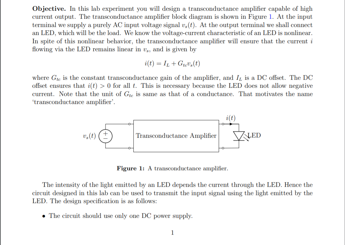
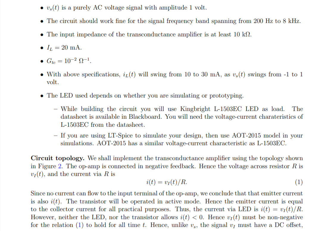
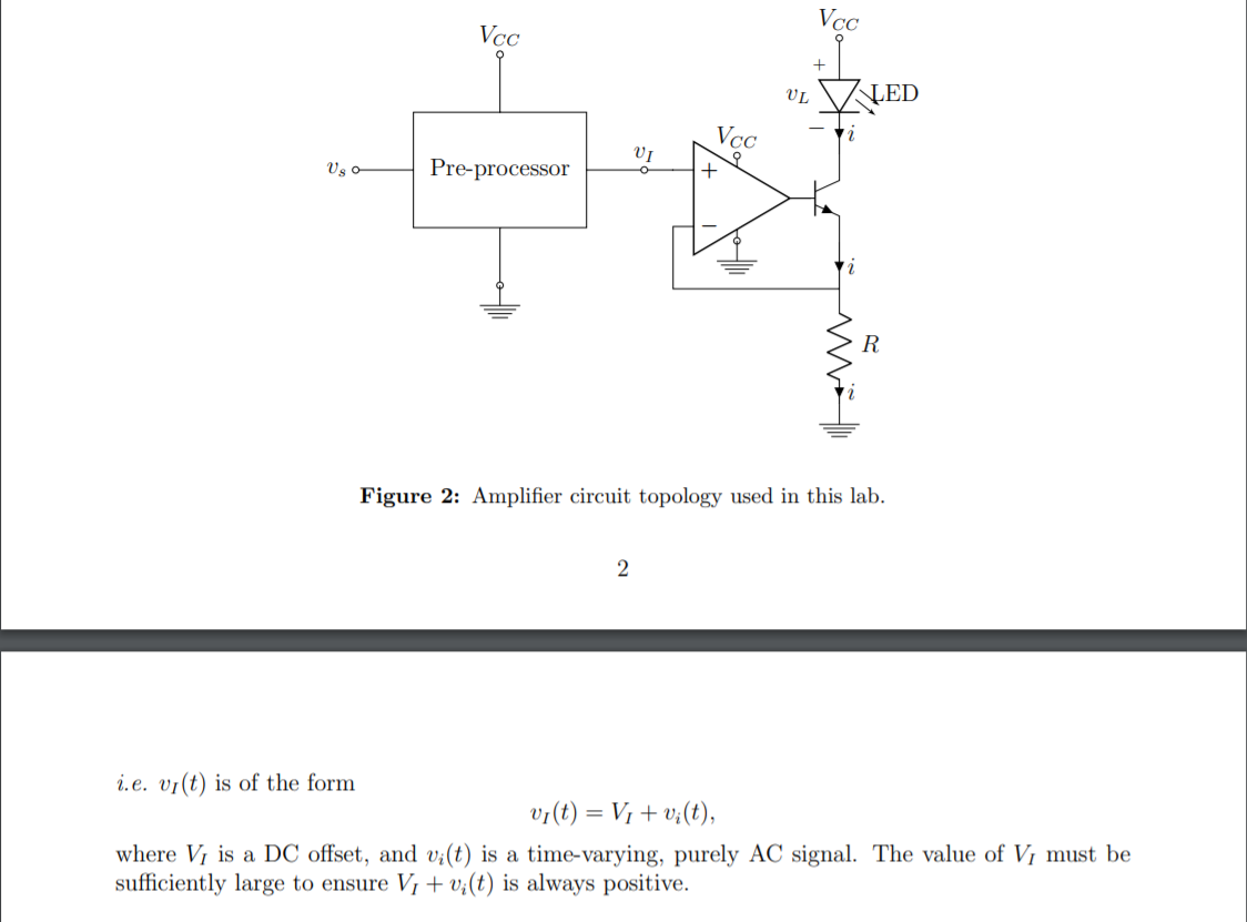
Objective. In this lab experiment you will design a transconductance amplifier capable of high current output. The transconductance amplifier block diagram is shown in Figure 1. At the input terminal we supply a purely AC input voltage signal vs(t). At the output terminal we shall connect an LED, which will be the load. We know the voltage-current characteristic of an LED is nonlinear. In spite of this nonlinear behavior, the transconductance amplifier will ensure that the current i flowing via the LED remains linear in vs, and is given by i(t) = I1 +Gtevy(t) where Gte is the constant transconductance gain of the amplifier, and IL is a DC offset. The DC offset ensures that i(t) > 0 for all t. This is necessary because the LED does not allow negative current. Note that the unit of Gte is same as that of a conductance. That motivates the name 'transconductance amplifier'. i(t) vy(t) Transconductance Amplifier LED Figure 1: A transconductance amplifier. The intensity of the light emitted by an LED depends the current through the LED. Hence the circuit designed in this lab can be used to transmit the input signal using the light emitted by the LED. The design specification is as follows: The circuit should use only one DC power supply. 1 vy(t) is a purely AC voltage signal with amplitude 1 volt. The circuit should work fine for the signal frequency band spanning from 200 Hz to 8 kHz. The input impedance of the transconductance amplifier is at least 10 kN. IL = 20 mA. Gte = 10-212-1. With above specifications, iz(t) will swing from 10 to 30 mA, as vs(t) swings from -1 to 1 volt. The LED used depends on whether you are simulating or prototyping. While building the circuit you will use Kingbright L-1503EC LED as load. The datasheet is available in Blackboard. You will need the voltage-current charateristics of L-1503EC from the datasheet. - If you are using LT-Spice to simulate your design, then use AOT-2015 model in your simulations. AOT-2015 has a similar voltage-current characteristic as L-1503EC. Circuit topology. We shall implement the transconductance amplifier using the topology shown in Figure 2. The op-amp is connected in negative feedback. Hence the voltage across resistor R is vi(t), and the current via R is i(t) = vi(t)/R. (1) Since no current can flow to the input terminal of the op-amp, we conclude that that emitter current is also i(t). The transistor will be operated in active mode. Hence the emitter current is equal to the collector current for all practical purposes. Thus, the current via LED is i(t) = vi(t)/R. However, neither the LED, nor the transistor allows i(t) 0 for all t. This is necessary because the LED does not allow negative current. Note that the unit of Gte is same as that of a conductance. That motivates the name 'transconductance amplifier'. i(t) vy(t) Transconductance Amplifier LED Figure 1: A transconductance amplifier. The intensity of the light emitted by an LED depends the current through the LED. Hence the circuit designed in this lab can be used to transmit the input signal using the light emitted by the LED. The design specification is as follows: The circuit should use only one DC power supply. 1 vy(t) is a purely AC voltage signal with amplitude 1 volt. The circuit should work fine for the signal frequency band spanning from 200 Hz to 8 kHz. The input impedance of the transconductance amplifier is at least 10 kN. IL = 20 mA. Gte = 10-212-1. With above specifications, iz(t) will swing from 10 to 30 mA, as vs(t) swings from -1 to 1 volt. The LED used depends on whether you are simulating or prototyping. While building the circuit you will use Kingbright L-1503EC LED as load. The datasheet is available in Blackboard. You will need the voltage-current charateristics of L-1503EC from the datasheet. - If you are using LT-Spice to simulate your design, then use AOT-2015 model in your simulations. AOT-2015 has a similar voltage-current characteristic as L-1503EC. Circuit topology. We shall implement the transconductance amplifier using the topology shown in Figure 2. The op-amp is connected in negative feedback. Hence the voltage across resistor R is vi(t), and the current via R is i(t) = vi(t)/R. (1) Since no current can flow to the input terminal of the op-amp, we conclude that that emitter current is also i(t). The transistor will be operated in active mode. Hence the emitter current is equal to the collector current for all practical purposes. Thus, the current via LED is i(t) = vi(t)/R. However, neither the LED, nor the transistor allows i(t)Step by Step Solution
There are 3 Steps involved in it
Step: 1

Get Instant Access to Expert-Tailored Solutions
See step-by-step solutions with expert insights and AI powered tools for academic success
Step: 2

Step: 3

Ace Your Homework with AI
Get the answers you need in no time with our AI-driven, step-by-step assistance
Get Started


