

Question: Please help thank you Introduction In this lab, you need to employ Always blocks, If statements, and For loops, as you have learned in this
Please help thank you
Introduction
In this lab, you need to employ Always blocks, If statements, and For loops, as you
have learned in this lab session. The module should be implemented on this assignment is a
Priority Encoder.
Priority Encoder
A priority encoder is a module with n inputs that maps to n outputs to represent input as
a binary code in output. You can look to this as one nbit input and one nbit output. The
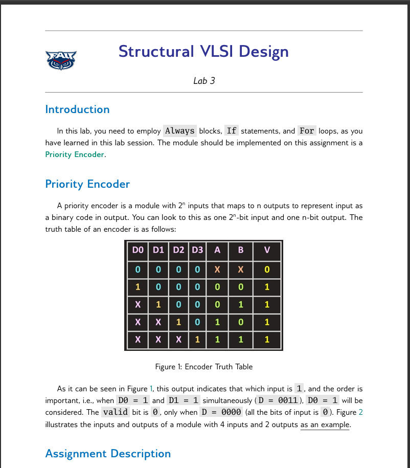
truth table of an encoder is as follows:
Figure : Encoder Truth Table
As it can be seen in Figure this output indicates that which input is and the order is
important, ie when D and D simultaneously D D will be
considered. The valid bit is only when D all the bits of input is Figure
illustrates the inputs and outputs of a module with inputs and outputs as an example.
Assignment Description
Design a Verilog module that implements a to priority encoder. The encoder will
take one bit input and output one bit binary code representing the highest priority input
that is active logic Inputs have a priority such that the least significant bit LSB has the
highest priority, and the most significant bit MSB has the lowest priority. In other words, for
example, when D but D the value of other left bits D D
D is not important, and output should be in a bbit binary, ie Y
Lab Structural VLSI Design
Figure : Encoder Inputs and Outputs
Ports
The module should have the following inputs and outputs:
D : INPUT. A single bit input where each bit represents a different input signal. Only
one input will be active at a time.
Y : OUTPUT. A single bit output representing the binary code of the highest priority
input that is active.
valid : OUTPUT. A bit output that is high if any input is active ie at least one
bit of A is and low otherwise.
Test Cases of the Simulation
D h Y b and valid
D h Y b and valid
D h Y b and valid
D h Y b and valid
D h Y b and valid
D h Y b and valid
D h Y b and valid
D h Y b and valid
D h Y b and valid
Lab Structural VLSI Design
What to Submit
For the labs, you have to prepare just a single PDF file as your lab report. The lab report
should contain these materials:
The waveform of the output. Take a screenshot from the waveform, and put it in the
waveform section of the report.
The schematic of the design. Take a screenshot from the schematic, and put it in the
schematic section of the report.
Your Verilog code of the design. Copy all the lines of your design code to your report
in a Microsoft Word document, or if you are using LATEX, you can use the listings
package to put your code in a document, which is the recommended way.
Your Verilog code of the testbench. Copy all the lines of your testbench code to
your report in a Microsoft Word document, or if you are using LATEX, you can use the
listings package to put your code in a document, which is the recommended way.
Final Notes
You must utilize a behavioral design. No other design, like gatelevel or data flow is
acceptable, and will get a ZERO grade. You should use For loops and if statements,
all in an Always block.
You can only upload a PDF file. If you are using Microsoft Word, convert it to a PDF file
and upload it If you are using LATEX for the assignments, just upload the generated PDF
file.
Writing any other information on the lab report is not mandatory. You can put only those
four sections in your lab report, or you can add some additional information on your file.
Its up to yourselves, and no grades would have been assigned to additional information
and explanation.
The waveform SHOULD be as clear as it can be The waveforms of the assignments that
dont comply with the "Beautifying Waveform" section in the lab will result to losing
the points of the waveform part.
Dont forget to set your testbench as Top Module before the simulation, or you will get
X s at the output, and you will lose the points of the waveform part.
Hint: If your Verilog testbench file in the Simulation Sources part of the Vivado, Sources,
is not boldface, rightclick on it and select Set as Top If this option is disabled
grayed out it means that your file has already been set as a top simulation source.
Step by Step Solution
There are 3 Steps involved in it
1 Expert Approved Answer
Step: 1 Unlock

Question Has Been Solved by an Expert!
Get step-by-step solutions from verified subject matter experts
Step: 2 Unlock
Step: 3 Unlock